Adaptive camera and illuminator eyetracker

a technology of eye tracking and adaptable camera, which is applied in the field of adaptable camera and illuminator eye tracking device, can solve the problems of small time delay, detriment to accuracy, and inability to carry out uninterrupted eye tracking based on just one of these imaging modes, so as to reduce the number of evaluations of image quality metric and reduce the number of times

Active Publication Date: 2010-12-30
TOBII TECH AB
View PDF7 Cites 104 Cited by
  • Summary
  • Abstract
  • Description
  • Claims
  • Application Information

AI Technical Summary

Benefits of technology

[0032]By virtue of its hierarchic nature, the proposed method for updating the selection of an camera-illuminator combination is economical in so far as it limits the number of evaluations of the image quality metric. In a typical computer implementation of the method, this number is likely to influence the computational complexity. The switching between reference illuminators (step iv)) does not require any evaluation of the quality metric.
[0033]The proposed method also minimises the number of times a camera is temporarily taken out of duty to acquire test images, which interrupts the gaze tracking. This may occur, for instance, when the selection of imaging mode is reassessed (step ii)) by acquiring a test image using the currently active camera and a currently inactive illuminator (one corresponding to the other imaging mode than that currently selected). As regards the reassessment of the camera selection (step iii)), the test images on which the decision is based may be acquired in a dual camera mode, which means that the gaze tracking can be pursued without interruption.

Problems solved by technology

In a given situation, the respective images may be of different quality, and it may even be impossible to carry out an uninterrupted gaze tracking based on just one of these imaging modes.
If two reference illuminators are used simultaneously, however, coexisting glints will mutually blur the measurements by reflections and the like.
If the reference illuminators are used alternately (e.g., by time interlacing), then a small time delay will necessarily separate the two images, to the detriment of the accuracy, particularly if the delay falls in the duration of a saccade.
The delay also makes the eye tracking slower.
A similar drawback becomes noticeable if the bright-pupil image is used for providing an initial guess in the process of finding the location of the pupil center in the dark-pupil image.
Particularly annoying are head movements that change the angle between the head and the camera of the eye tracker, because this may introduce obscuring objects into the line of sight from the reference illuminator to the eye or into the line from the eye to the camera.
Notably, spectacle frames, eyelashes, eyebrows, nose and protruding brow bones may cause problems of this kind.
This is detrimental to image contrast and makes it more difficult to find the location of the reflection of the light source.
The problem is most severe in the case of the coaxial, smaller illuminator, which is further shrunk by reflection in the convex cornea, as seen above.

Method used


Image

  • Adaptive camera and illuminator eyetracker
  • Adaptive camera and illuminator eyetracker
  • Adaptive camera and illuminator eyetracker

Examples


Embodiment Construction

I. Eye Tracker Comprising One Reference Illuminator

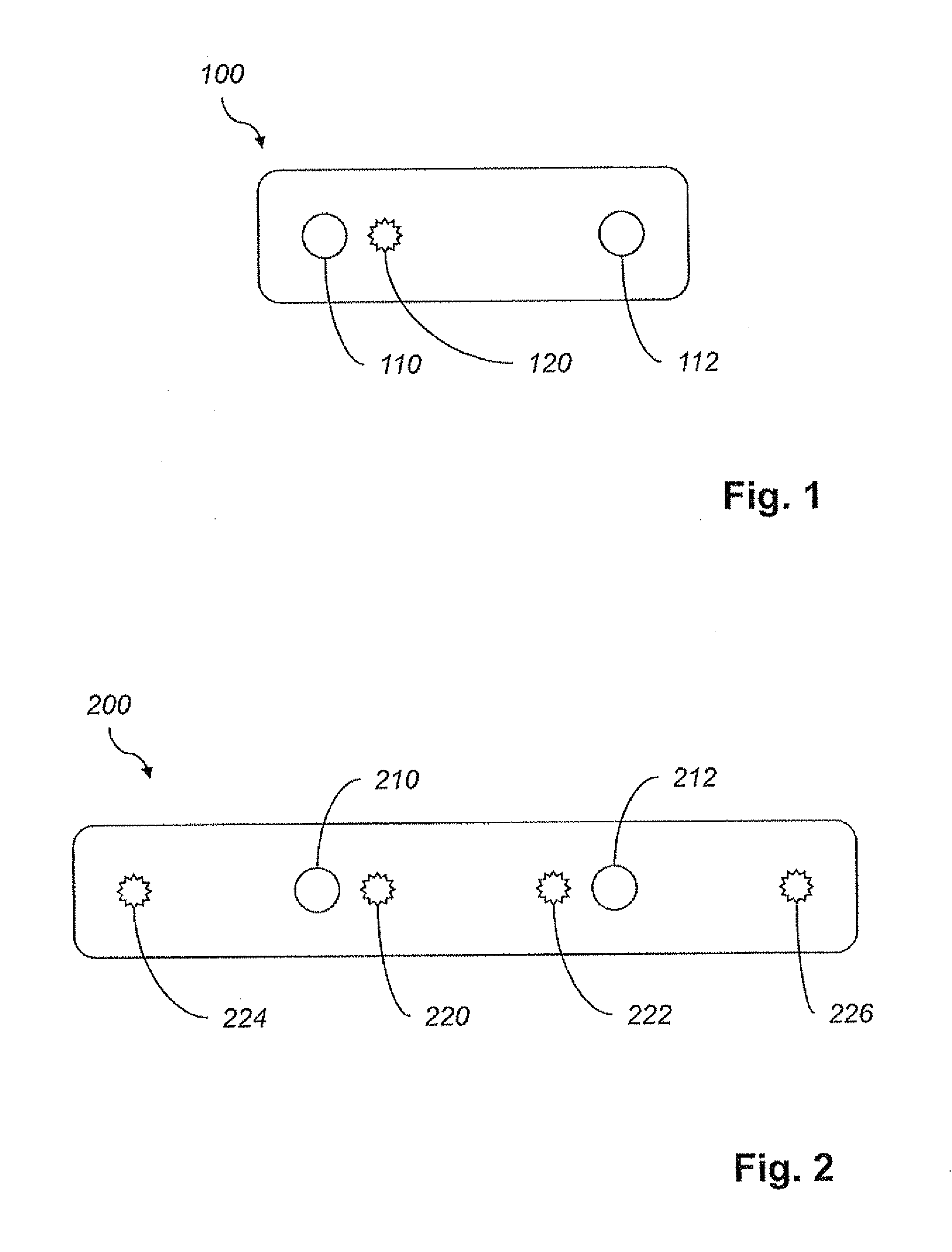
[0044]FIG. 1 shows a combined camera and illuminator arrangement 100. The arrangement 100 may be part of an eye tracker, in the sense that it is controllable by an eye tracker, and may even be embodied in the same physical unit as such device. It is also envisioned that an eye tracking system may comprise a processor and the arrangement 100 of FIG. 1.

[0045]The arrangement 100 comprises a reference illuminator 120 and a first camera 110 provided coaxially with the reference illuminator 120 in the sense that the optic axes of the two devices are parallel and the distance between them is small in relation to the overall length scale. The reference illuminator 120, which preferably is adapted to emit (near) infrared light from a point-shaped aperture, and the first camera 110 are arranged so closely to one another that it is possible to image the retinal retro-reflection (bright-pupil effect) of the reference illuminator 120. In some co...


PUM


Abstract

An eye tracker includes at least one illuminator for illuminating an eye, at least two cameras for imaging the eye, and a controller. The configuration of the reference illuminator(s) and cameras is such that, at least one camera is coaxial with a reference illuminator and at least one camera is non-coaxial with a reference illuminator. The controller is adapted to select one of the cameras to be active to maximize an image quality metric and avoid obscuring objects. The eye tracker is operable in a dual-camera mode to improve accuracy. A method and computer-program product for selecting a combination of an active reference illuminator from a number of reference illuminators, and an active camera from a plurality of cameras are provided.

Description

RELATED APPLICATIONS[0001]This application claims the benefit of U.S. Provisional Application Ser. No. 61 / 166,012 filed Apr. 2, 2009, the entire contents of which are incorporated herein by reference.FIELD OF THE INVENTION[0002]The present invention relates to a device for illuminating and imaging an eye. More precisely, the invention provides an adaptive pupil-center-corneal-reflection (PCCR) eye tracking system comprising multiple cameras.BACKGROUND OF THE INVENTION[0003]A PCCR-based approach to determining the gaze of an eye may use an image of the eye either in its bright-pupil condition (a retinal retro-reflection complements the iris image) or dark-pupil condition (a cornea-scleral reflection complements the iris image). In a given situation, the respective images may be of different quality, and it may even be impossible to carry out an uninterrupted gaze tracking based on just one of these imaging modes. Therefore, to be able to choose the optimal mode, some available eye tr...

Claims


Application Information

Patent Timeline
Patent Type & Authority Applications(United States)
IPC IPC(8): H04N7/18
CPCA61B3/113G06V40/19A61B3/14A61B3/0025A61B3/145A61B3/0008
Inventor BLIXT, PETERHOGLUND, ANDERSTROILI, GUNNARELVESJO, JOHNSKOGO, MARTEN
Owner TOBII TECH AB
Why Eureka
Try Eureka