Ceiling fan

a ceiling fan and fan body technology, applied in the field of ceiling fans, can solve the problems of difficulty in unscrewing the long screws holding the fan in place, disconnection from the house circuit, and the inability to readily detach the ceiling fan from its current substantial position, and achieve the effect of convenient and convenient attachment or removal

Inactive Publication Date: 2010-12-30
CRINER JERRY D +1
View PDF13 Cites 49 Cited by
  • Summary
  • Abstract
  • Description
  • Claims
  • Application Information

AI Technical Summary

Benefits of technology

[0025]The primary object of our invention is to provide a ceiling fan device which is easily and conveniently attachable to or removable from a ceiling position and which is safe while doing so.

Problems solved by technology

In such instances, a ceiling fan was not intended to be readily detachable from its current substantial position.
Obviously, the major steps in removing a ceiling fan are the disconnection from the house circuit and the difficulty in unscrewing the long screws holding the fan in place.

Method used


Image

  • Ceiling fan
  • Ceiling fan
  • Ceiling fan

Examples


Embodiment Construction

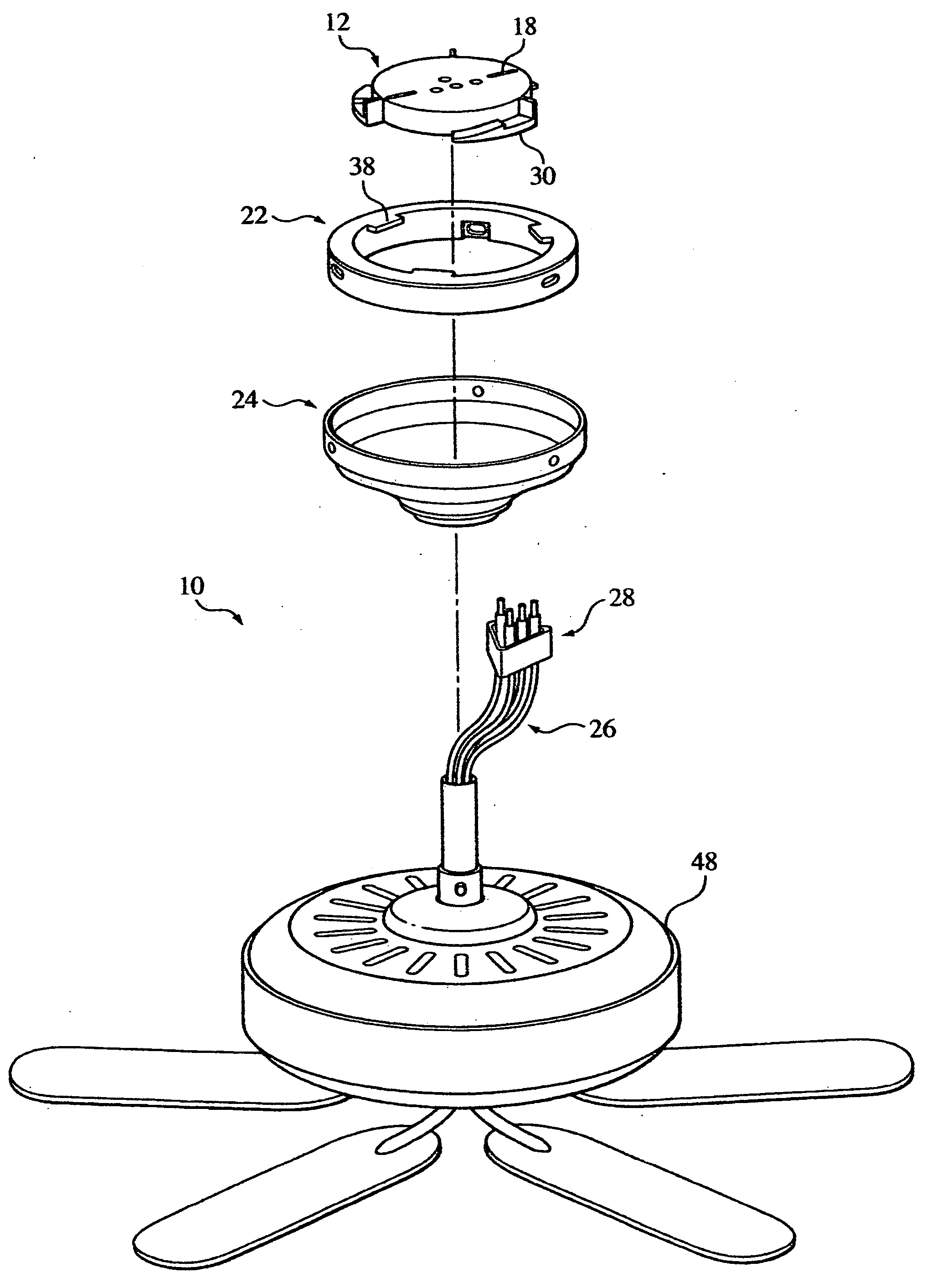
[0045]In FIG. 1 we describe one embodiment of a ceiling fan device 10, generally, according to our invention. In this exploded view of FIG. 1, we show the major components of our ceiling fan 10 as they would be arranged in the most easily understood positions and order for assembly and installation against a ceiling of a house.

[0046]The uppermost component is a first bracket member as shown by a ceiling plate 12, generally, which holds the entire ceiling fan device in place against a ceiling, 14, generally, by means of screws 16 extending thru slots 18 as shadow in FIG. 7.

[0047]As we have planned for easy handling and movement of our ceiling fan, we plan a ceiling plate 12 to be placed securely against the ceiling in any room where we want to feel comfortable with a ceiling fan 12, so that we secure only a ceiling plate 12 in position. If we have access to a sturdy beam 20, generally, we are able to provide means for the screws 18 to be in a more secure position.

[0048]FIG. 1 shows t...


PUM


Abstract

A ceiling fan comprising bracket components which are easily and conveniently attachable in a suitable position by one person thru simple operation and adjustment of mechanical parts. Attachment components are removably secured to a ceiling plate connected to a house circuit in an initial room then capable of easy removal therefrom and attachable to a ceiling plate installed in another room. A fan circuit is connectable to a house circuit by simple plug members and fan unit is quickly positionable into a secure position by position against and rotation of cooperable components with ceiling plate.

Description

FIELD OF THE INVENTION[0001]Our invention relates to ceiling fans, particularly to ceiling fans which are constructed to be easily and conveniently attachable into position and easily and conveniently removable from an attached position. Further, our invention relates to ceiling fans which are easily and conveniently handled by one person in either an attachable operation or a removable operation. Still more particularly, our invention relates to ceiling fans which do not involve the attachment of security-related components when being attached to the ceiling, or the removal of such security-related components, such as a screw, or nut and bolt, when being removed from position. The attachment of our fan is easy and simple, and the only actions required are the plugging into a house circuit and a slight rotation of the fan to obtain the attachment into place. The construction of the fan permits the entire operation to be performed by one person, and safely.BACKGROUND OF THE INVENTION...

Claims


Application Information

Patent Timeline
Patent Type & Authority Applications(United States)
IPC IPC(8): F04D29/60A47B96/06
CPCF04D29/601F04D25/088
Inventor CRINER, JERRY D.YOUNG, JODI B.
Owner CRINER JERRY D
Why Eureka
Try Eureka