Conveyor tunnel oven

a tunnel oven and conveyer technology, applied in baking ovens, baking, food science, etc., can solve the problems of difficult mechanical attachment and detachment, painful skin burning, and the forward surface of the outer panel produces, and achieves convenient and convenient transportation, convenient and convenient attachment and detachment, and advantageous protection of skin contacts. , the effect of preventing burning

Active Publication Date: 2021-10-19
WOLFE ELECTRIC
View PDF70 Cites 0 Cited by
  • Summary
  • Abstract
  • Description
  • Claims
  • Application Information

AI Technical Summary

Benefits of technology

[0012]In use of the instant invention, an oven operator may easily and conveniently carry the invention's “J” hook component, utilizing distal end of its upper tail component in the manner of a carry handle. Thereafter, the user may manually orient the “J” hook component so that the tail's downwardly opening throat upwardly overlies the upturned distal ends of the “L” hooks' foot components. Thereafter, the “J” hook may be manually lowered until such feet nestingly enter the throat of the “J” hook's tail, advantageously hookingly engaging the “J” hook with the “L” hooks.
[0013]In such assembled configuration, the “J” hook's panel configured stem component advantageously functions as a auxiliary burn protecting wall which forwardly overlies the front panel's forward surface to form a heat insulating air gap. During cooking use of the oven, the front surface of the “J” hook's stem component remains substantially cooler than the front surface of the front panel's rearwardly underlying front surface, advantageously protecting skin contacts from burning. Multiple “J” hook configured auxiliary panels are easily and conveniently attachable and detachable to a stacked series of conveyor tunnel ovens.

Problems solved by technology

During cooking use of such ovens, the attachable and detachable front panels often become heated to a temperature at which physical contact by an operator against the outer forward surface of the panel produces painful skin burning.
While such protective auxiliary panels define protective and insulating air gaps, such auxiliary panels are often difficult to mechanically attach and detach, and such auxiliary panels often mechanically interfere with access to underlying fasteners which are provided for facilitating attachment and detachment of the removable panel.

Method used


Image

  • Conveyor tunnel oven
  • Conveyor tunnel oven
  • Conveyor tunnel oven

Examples


Embodiment Construction

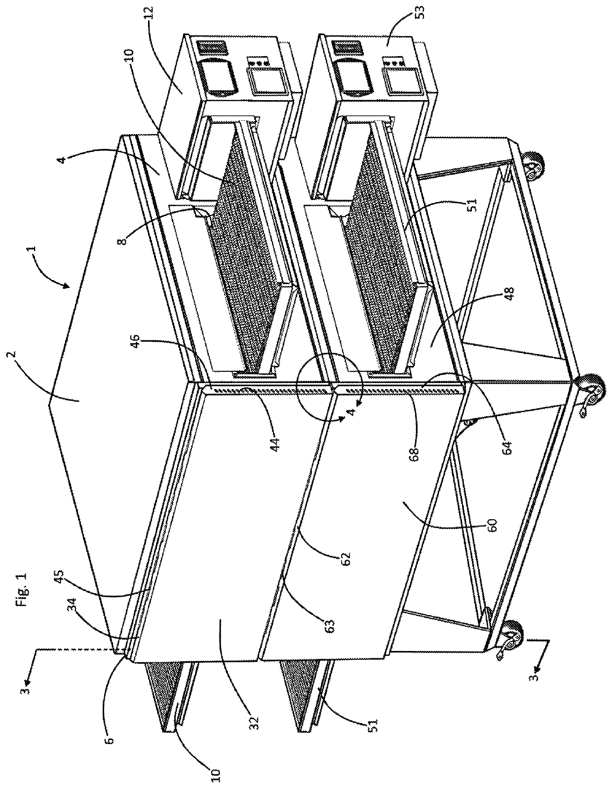
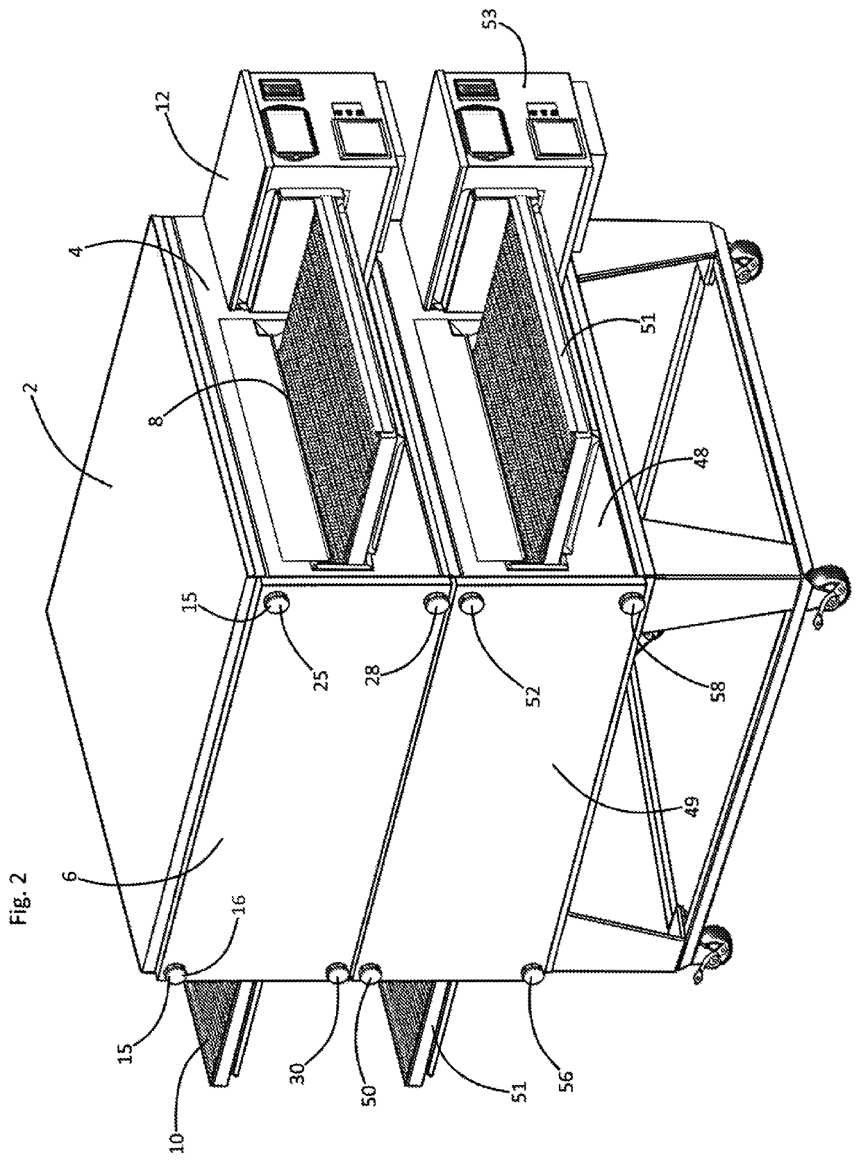
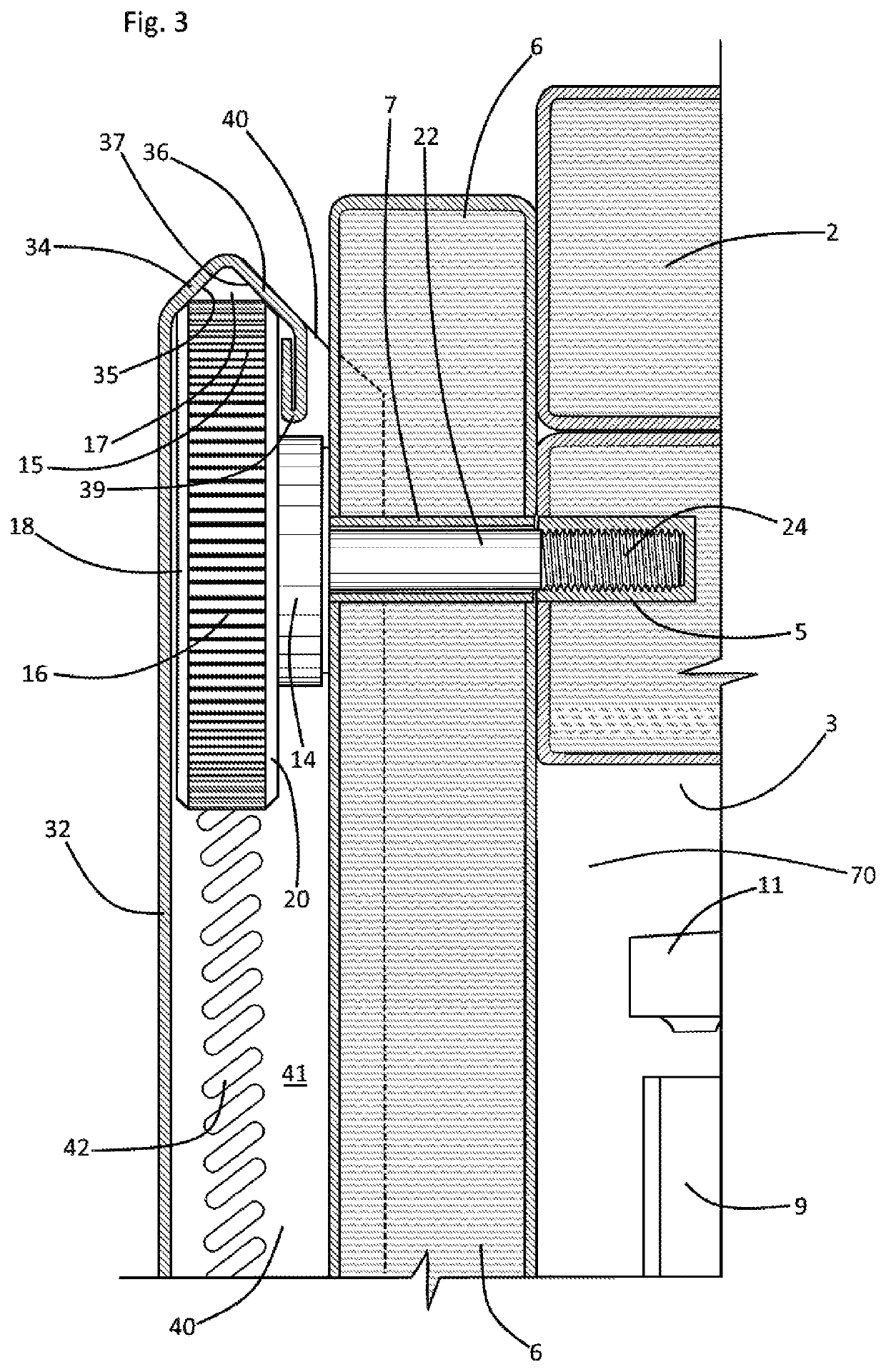
[0020]Referring now to the drawings, and in particular to Drawing FIG. 1, a preferred embodiment of the instant inventive conveyor tunnel oven is referred to generally by Reference Arrow 1. The oven 1 has an upper wall or ceiling 2, a lower wall or floor (not depicted within views) underlying the upper wall 2, and a longitudinal wall 4. Referring further simultaneously to FIGS. 2-4, the oven's case component further includes an oppositely longitudinal wall 3, a forward opening 70, and a rear wall (not depicted within views) positioned rearwardly from the forward opening 70. Longitudinal and oppositely longitudinal food passage ports 8 and 9 further open the interior of the baking case component at its longitudinal and oppositely longitudinal walls 4 and 3, and a grate type continuous loop conveyor 10 extends through the baking case to protrude from such ports. Heated air jetting finger ducts 11 are preferably arrayed within the case above and below the conveyor 10 for impingement ai...


PUM


Abstract

A conveyor tunnel oven incorporating forwardly opening baking case having a rear wall, a longitudinal wall, an oppositely longitudinal wall, an upper wall and a lower wall, the case being further opened by a longitudinal food passage port and an oppositely longitudinal food passage port; a continuous loop conveyor within the baking case, the conveyor extending to the longitudinal and oppositely longitudinal food passage ports; a panel having a forward surface, the panel being fitted for closing the baking case's forward opening; a pair of “L” hooks, each “L” hook including a helically threaded stem and a foot, the hooks positioning the panel over the baking case's forward opening; and a “J” hook having a stem and a tail, the tail having a distal end and a throat engaging the “L” hooks' feet so that the “J” hook's stem overlies the panel's forward surface.

Description

FIELD OF THE INVENTION[0001]This invention relates to conveyor tunnel ovens. More particularly, this invention relates to conveyor tunnel ovens which incorporate an attachable and detachable panel type front wall, and which incorporate a forwardly overlying heat shielding wall.BACKGROUND OF THE INVENTION[0002]Conveyor tunnel ovens are known to incorporate a panel configured front wall which is alternatively attachable and detachable. During cooking use of such ovens, the attachable and detachable front panels often become heated to a temperature at which physical contact by an operator against the outer forward surface of the panel produces painful skin burning.[0003]To lessen the risk of such skin burning contact, protective auxiliary panels are known to be attached to the oven at a position forwardly overlying the removable front panel. While such protective auxiliary panels define protective and insulating air gaps, such auxiliary panels are often difficult to mechanically attach...

Claims


Application Information

Patent Timeline
Patent Type & Authority Patents(United States)
IPC IPC(8): A21B1/48A21B1/26
CPCA21B1/48A21B1/26
Inventor KESTER, DALEMARTINEZ, SKYLER
Owner WOLFE ELECTRIC
Why Eureka
Try Eureka