Suture passing instrument and method

a technology of suturing instruments and needles, applied in the field of surgical stitching devices, can solve the problems of protruding needles being caught in tissue, limited maneuverability of most currently available suturing instruments,

Active Publication Date: 2010-12-30
CETERIX ORTHOPAEDICS
View PDF112 Cites 37 Cited by
  • Summary
  • Abstract
  • Description
  • Claims
  • Application Information

AI Technical Summary

Problems solved by technology

Arthroscopic rotator cuff repair is one example of a technically challenging procedure that requires the placement of sutures in difficult to reach regions, as well as requiring precise placement of sutures.
Furthermore, most currently available suturing instruments are limited in their ability to be maneuvered, particularly over thicker tissue regions, and may require additional space so that additional surgical instruments, including forceps or other graspers, may be used.
At least one end of the needle protrudes from one or the other jaw at all times. The protruding needle may become caught in tissue, a problem that is exacerbated in difficult to access regions and regions offering limited maneuverability, such as the subacromial space of the jaw.

Method used


Image

  • Suture passing instrument and method
  • Suture passing instrument and method
  • Suture passing instrument and method

Examples


Embodiment Construction

[0075] Described herein are various embodiments of suture passers for passing a suture through tissue, and components of suture passers that particularly enhance use. In general, the suture passers described herein are continuous suture passers that are configured to pass a suture back and forth through a tissue without having to reload the device. Thus, these devices may be used for continuous stitching of tissue.

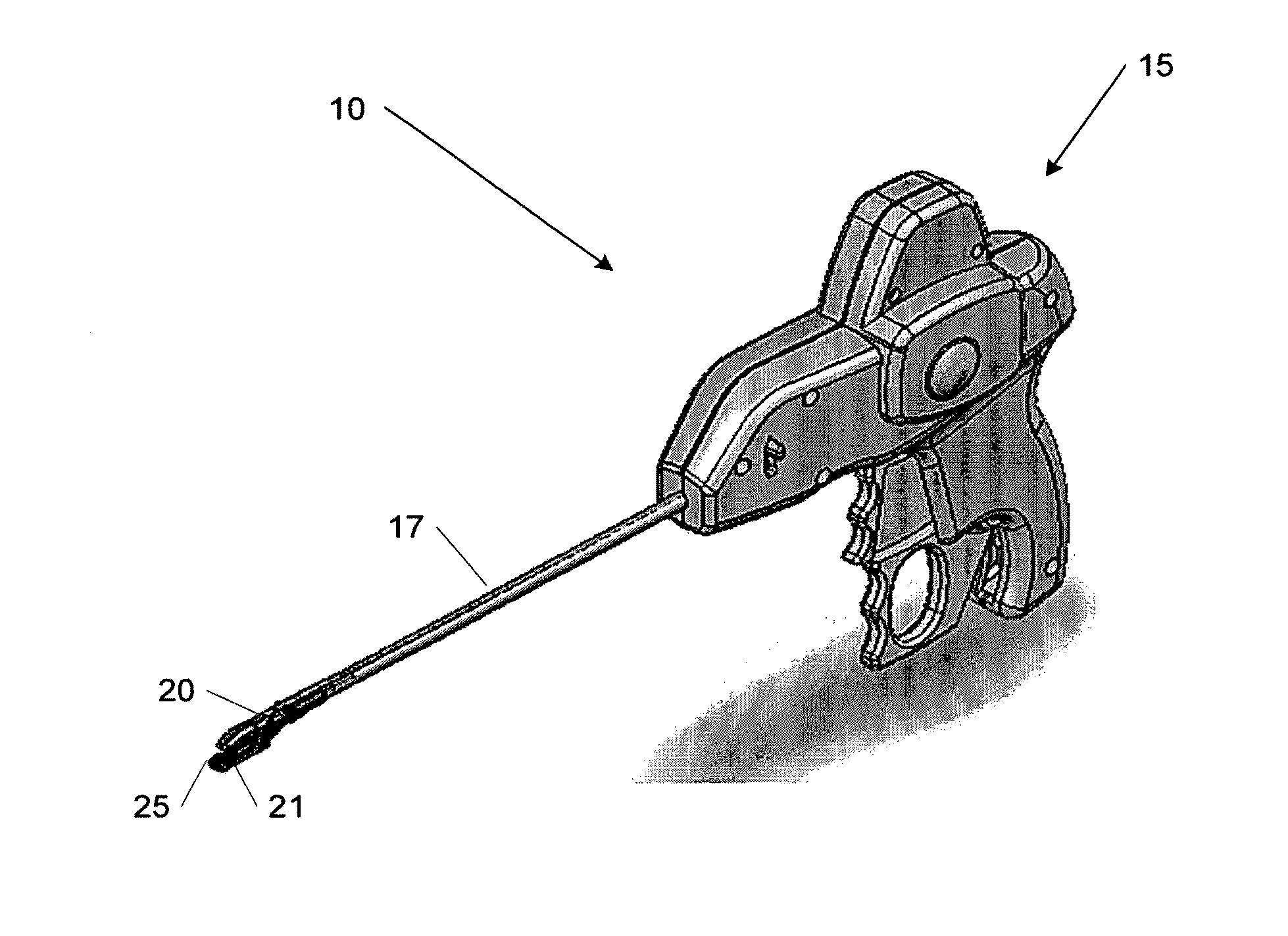
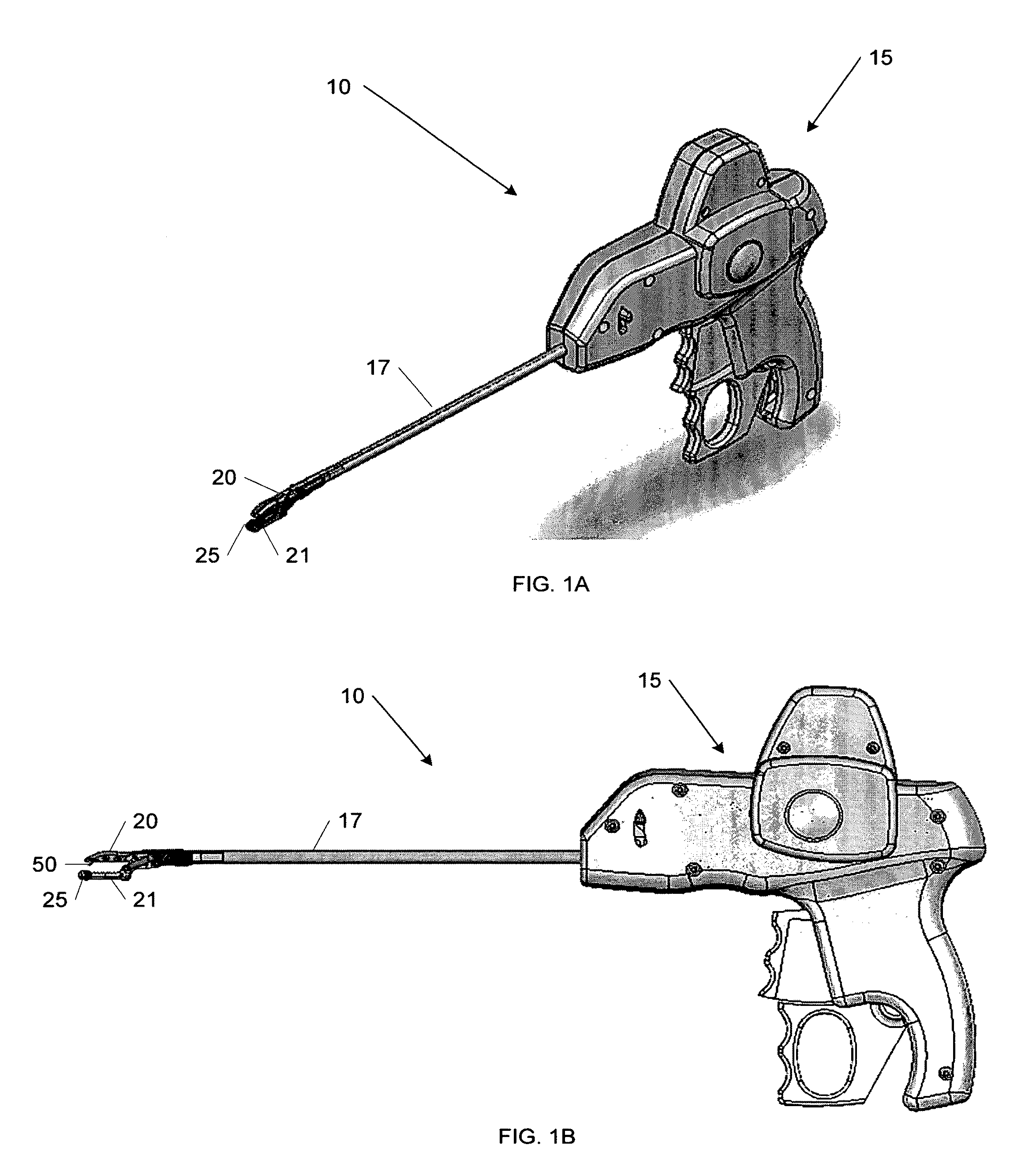
[0076]FIG. 1A illustrates a first embodiment of a continuous suture passer 10, including some of the enhanced features described herein, which may include, but is in no way limited to, a tissue penetrator (not shown), shuttle (not shown), reciprocating parallel-opening first and second jaws 20 and 21, jaw lock (not shown), and lower-jaw shuttle retainer seat 25. FIG. 1B shows a planar view of the device 10, including the parallel-opening jaws 20 and 21, tissue penetrator 50, and lower-jaw shuttle retainer seat 25.

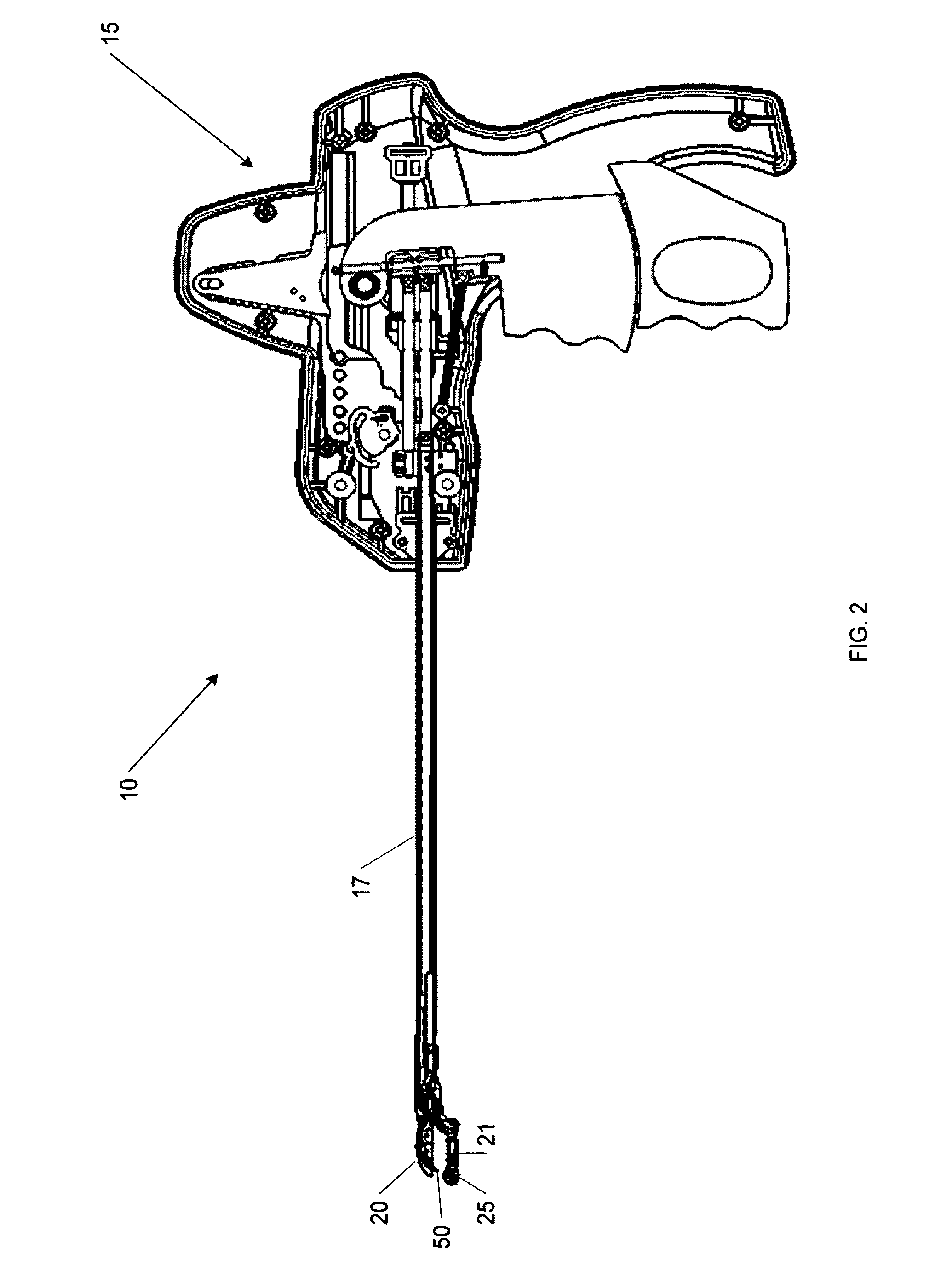
[0077]FIG. 2 illustrates a cross-sectional view of a first...


PUM


Abstract

In one embodiment, a continuous suture passer device may include a first jaw, a second jaw, a tissue penetrator which may penetrate through tissue positioned between the first and second jaws, and a suture shuttle which may be releasably secured to the tissue penetrator and adapted to carry a suture. Further, the device may include an actuator which may manipulate at least one of the first or second jaws and the tissue penetrator, and the second jaw may have a suture shuttle retainer seat on which the suture shuttle may be releasably secured. The tissue penetrator may be movable towards the second jaw such that the suture shuttle carried by the tissue penetrator may be transferred to the shuttle retainer seat on the second jaw. Additionally, the first and second jaws may be substantially parallel to one another at any position to which the at least one jaw is manipulated. Additionally, the tissue penetrator may travel along an arcuate path from a first position, recessed within the first jaw, to a second position where the tissue penetrator extends through the tissue to be positioned in communication with the second jaw. Further, the at least one jaw may be manipulated such that it travels along a path that is substantially the same arcuate path traveled by the tissue penetrator. A method for passing a suture through tissue includes manipulation to transfer a suture shuttle adapted to carry a suture between a tissue penetrator and a second jaw.

Description

CROSS-REFERENCE TO RELATED APPLICATIONS [0001] This application claims the benefit of the filing dates of U.S. Provisional Patent Application Nos. 60 / 985,543 filed Nov. 5, 2007; 60 / 985,556 filed Nov. 5, 2007; 61 / 013,989 filed Dec. 14, 2007; 61 / 013,994 filed Dec. 14, 2007; 61 / 014,728 filed Dec. 18, 2007; 61 / 013,999 filed Dec. 14, 2007; 61 / 014,003 filed Dec. 14, 2007; 61 / 014,012 filed Dec. 14, 2007; 61 / 042,678 filed Apr. 4, 2008; and 61 / 127,658 filed May 14, 2008, the disclosures of each of the foregoing being incorporated herein by reference as if fully set forth herein.BACKGROUND OF THE INVENTION [0002] This invention relates to surgical stitching devices by which a stitch or continuous stitches may be made during surgery. [0003] Suturing instruments for assisting a medical practitioner in placing stitches during surgical procedures are particularly helpful in surgical procedures requiring the placement of secure and accurate sutures in difficult to access regions of the body. Instr...

Claims


Application Information

Patent Timeline
Patent Type & Authority Applications(United States)
IPC IPC(8): A61B17/04
CPCA61B17/0469A61B17/06004A61B17/06066A61B17/0625A61B2017/00831A61B2017/06009A61B2019/4857A61B2017/2912A61B2017/2917A61B2017/2926A61B2017/2944A61B2017/2946A61B2017/06042A61B2090/0811
Inventor SALIMAN, JUSTINSHAHOIAN, ERIKJASSO, ALEXANDERANASTAS, GEORGE
Owner CETERIX ORTHOPAEDICS
Why Eureka
Try Eureka