Apparatus, method, and system for monitoring leakage current and detecting fault conditions in electrical systems

a technology of leakage current and electrical system, applied in emergency protective arrangements, circuit arrangements, instruments, etc., can solve problems such as economic impracticality of low voltage us

Active Publication Date: 2011-01-13
MUSCO
View PDF30 Cites 29 Cited by
  • Summary
  • Abstract
  • Description
  • Claims
  • Application Information

AI Technical Summary

Benefits of technology

[0022]4. providing an optional bypass system which allows a qualified user to diagnose potential fault conditions, undesirable trends in leakage current measurements, and / or threshold violations in the electrical system.

Problems solved by technology

Disclosed herein are apparatus, methods, and systems for the continuous monitoring of leakage current in an electrical system that employs widely distributed electrical devices and utilizes relatively high voltage (e.g., 277-480 VAC) to operate them; particularly the type of electrical system with extended wire runs (which makes the use of low voltage economically impractical).

Method used


Image

  • Apparatus, method, and system for monitoring  leakage current and detecting fault conditions  in electrical systems
  • Apparatus, method, and system for monitoring  leakage current and detecting fault conditions  in electrical systems
  • Apparatus, method, and system for monitoring  leakage current and detecting fault conditions  in electrical systems

Examples


embodiment 1

B. Exemplary Method and Apparatus Embodiment 1

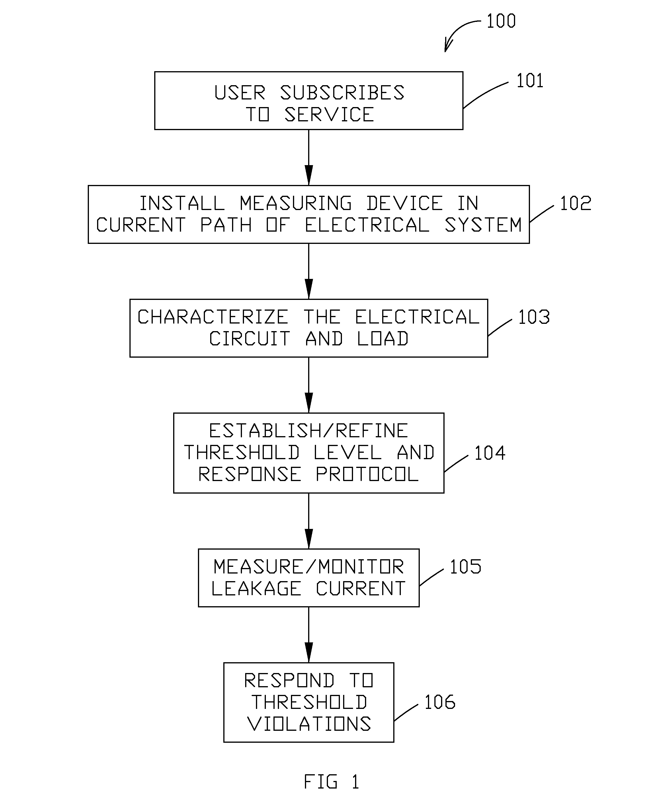
[0071]A more specific exemplary embodiment, utilizing aspects of the exemplary method described above, will now be described. This first exemplary embodiment describes the scenario in which a customer wants to subscribe to a monitoring service for a new electrical system (in this example, an outdoor sports lighting system—see FIGS. 5A and B) wherein both the lighting system and the monitoring service are available from the same provider.

[0072]According to this first embodiment, the customer (e.g., owner of the site, purchaser of the service, user of the electrical system, etc.) subscribes to the monitoring service (see step 101 of method 100) when purchasing the lighting system. As part of the purchasing agreement the user is instructed to visit the company's (hereafter referred to as Company X) subscription registration website and fill out the necessary subscription information. Webpage 700 (see FIG. 3) is a typical representation of t...

embodiment 2

C. Exemplary Method and Apparatus Embodiment 2

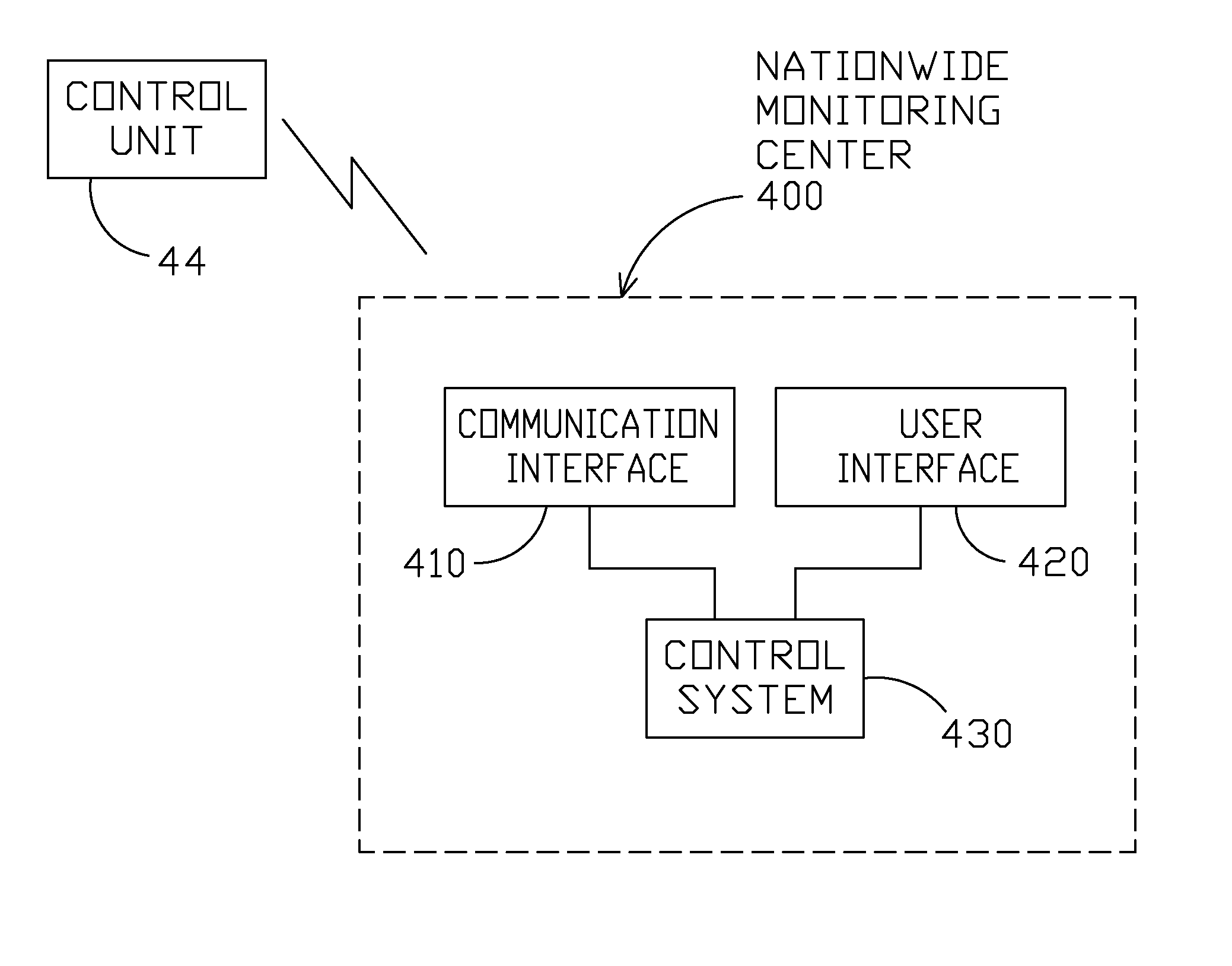
[0122]A second exemplary system is shown in FIG. 10 and illustrates the scenario in which a customer wants to monitor leakage current in (i) lighting circuits (in this example, street lights) and (ii) other electrical circuits (loads could include, for example, traffic lights, radar devices, crosswalk signals, motion sensors, timers, etc.). In the present embodiment it is possible for all electrical circuits, leakage current measuring equipment, and the monitoring service to be provided by Company X, however, for illustrative purposes it is assumed that the electrical systems are preexisting and Company X is supplying only the measuring equipment and monitoring service.

[0123]According to method 100, the user first subscribes to the monitoring service (see step 101). Step 101 is primarily the same for the present embodiment as for Exemplary Method and Apparatus Embodiment 1; one difference is that subscription is not automatic or otherwis...


PUM


Abstract

Disclosed herein are apparatus, methods, and systems for monitoring and detection of conditions indicative of an electrical fault for an electrical circuit or system. In one aspect, a central control can simultaneously monitor a plurality of geographically distributed electrical circuits or systems for conditions that have been predetermined to be indicative of an electrical fault or concern, and provide either some communication (e.g., a warning) or instruction (e.g., to terminate power) back to the monitored circuit/system, the owner/operator/user of the circuit/system, or both. The central control can collect, store, mine, and analyze data from the diverse monitoring of plural systems. A knowledge base can be built up over time and used to establish monitoring of the same, other circuits and systems, develop more accurate monitoring and communication of faults or concerns, and account for factors related to normal operation of a circuit or system.

Description

CROSS-REFERENCE TO RELATED APPLICATIONS[0001]This application claims priority under 35 U.S.C. §119 to provisional U.S. application Ser. No. 61 / 224,370 filed Jul. 9, 2009, hereby incorporated by reference in its entirety.I. BACKGROUND OF THE INVENTION[0002]The present invention relates to the active monitoring of leakage current to detect potential fault conditions and provide early warning of future potential fault conditions and / or leakage current measurements that exceed defined threshold settings. More specifically, the present invention relates to a leakage current monitoring service and the implementation and operation thereof to provide said detection and early warning.[0003]Electrical systems and devices are generally designed with various precautions in mind. These precautions typically fall into one of two categories: prevention of occurrences of hazardous or undesired events (e.g., by product testing, insulating energized electrical components from nearby conductive surfac...

Claims


Application Information

Patent Timeline
Patent Type & Authority Applications(United States)
IPC IPC(8): H02H3/08H01H31/12G08B21/00
CPCH01H83/02H05B37/034H02H3/347H02H3/042H05B47/22
Inventor CROOKHAM, JOE P.GORDIN, MYRONCHELCUN, DARRELL N.
Owner MUSCO
Why Eureka
Try Eureka