Antenna arrangement for multimode communication device

a multi-mode communication and antenna technology, applied in the direction of resonant antennas, separate antenna unit combinations, radiating element structure forms, etc., can solve the problems of easy interference or coupleing of antenna configurations typically used for certain bands with other antenna configurations used for other bands, and common antennas such as a planar design

Inactive Publication Date: 2011-01-20
GOOGLE TECH HLDG LLC
View PDF14 Cites 42 Cited by
  • Summary
  • Abstract
  • Description
  • Claims
  • Application Information

AI Technical Summary

Problems solved by technology

As wireless devices become exceedingly slimmer and greater demands are made for antennas operating on a diverse number of frequency bands, common antennas such as a Planar Inverted “F” Antenna (PIFA) design becomes impractical for use in such slim devices due to its inherent height requirements.
Antenna configurations typically used for certain bands can easily interfere or couple with other antenna configurations used for other bands.
Existing designs may have call drop issues or poor performance that relate to loading on antennas caused by hand grips on a portion of the phone or caused by loading caused by other loading conditions.
Furthermore, antennas designed for PCS bands are generally configured to be optimized across the entire PCS band which may not be ideal for a number of scenarios.
From the low band family of curves, it can be seen that substantial degradation of system efficiency (e.g., the data mode use case) is due simply to mismatch loss (as evidenced by a large delta between radiation and system efficiencies).
Although antenna systems are primarily designed for voice-centric devices, the more current devices shipping or being developed are not necessarily voice-centric.
Current antenna architectures or platforms with the antenna located at the bottom of the phone are highly optimized for talk mode and rather disadvantaged for many data modes of operation.
For a given hand grip, the efficiency degradation is more severe in the higher frequency bands.

Method used


Image

  • Antenna arrangement for multimode communication device
  • Antenna arrangement for multimode communication device
  • Antenna arrangement for multimode communication device

Examples


Embodiment Construction

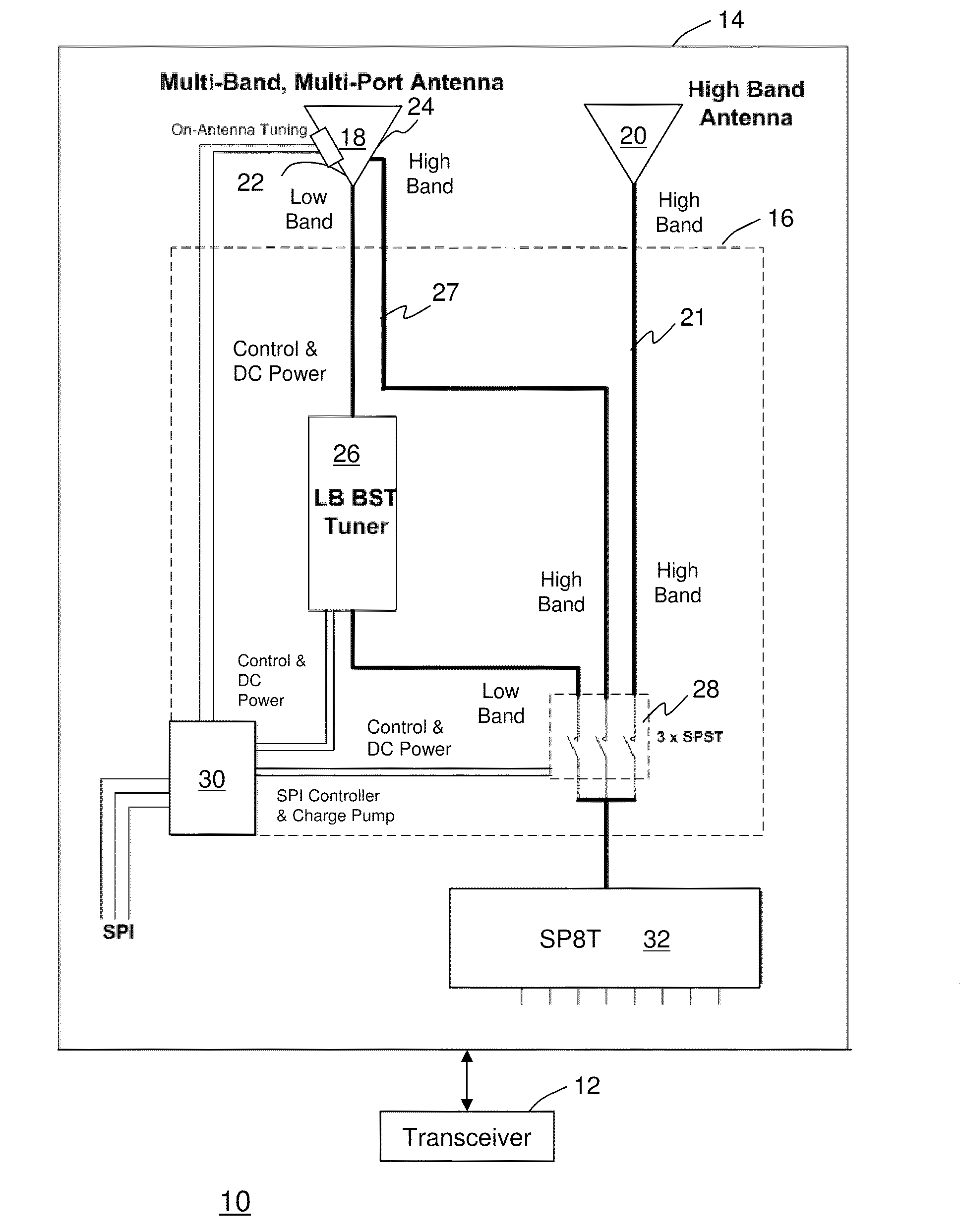
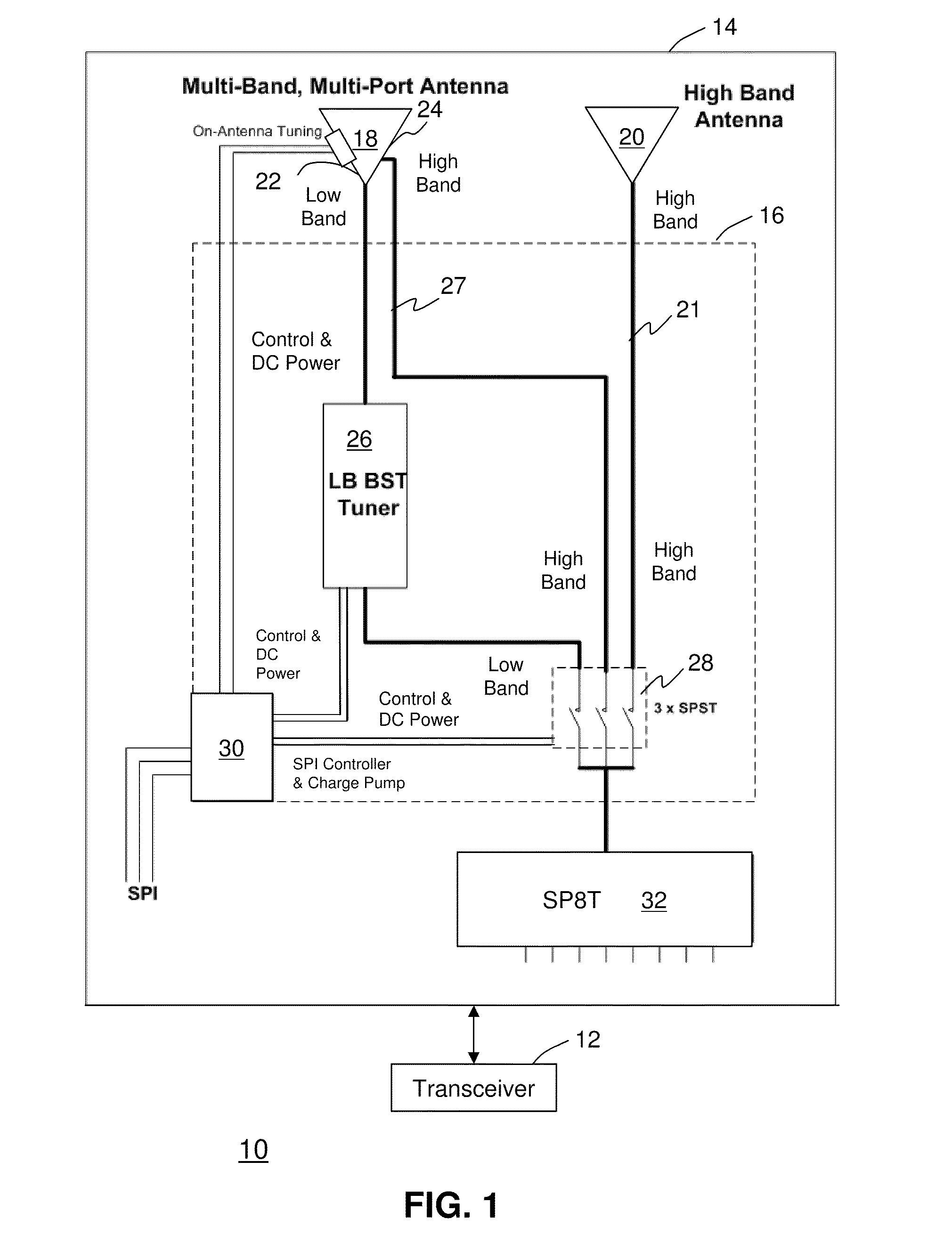
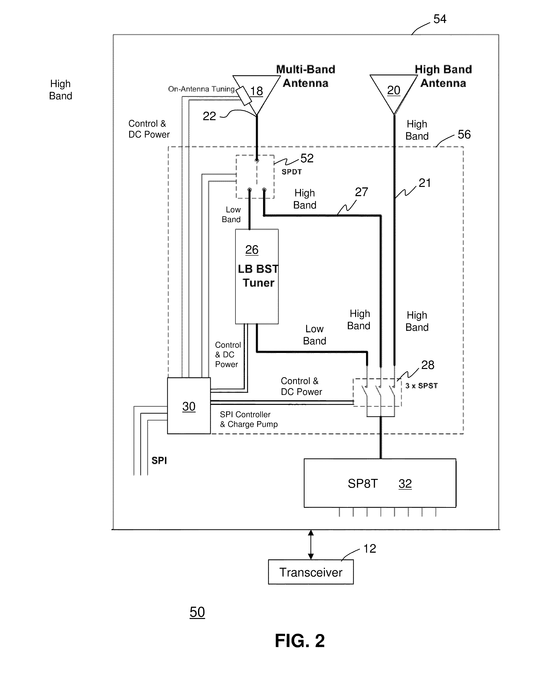
[0013]One embodiment of the present disclosure can entail an antenna arrangement for a multimode communication device having a first antenna designed primarily for operation in a low band below 1000 MHz and in predetermined modes for high bands above 1500 MHz, a second antenna designed to operate solely or only in the high bands, a Voltage Standing Wave Ratio (VSWR) tuner coupled to the first antenna, and a controller coupled to the VSWR tuner. The antenna arrangement can also entail a switching mechanism for selecting between the first antenna and the second antenna where the controller would be coupled to the switching mechanism and the tuner.

[0014]Another embodiment of the present disclosure can entail a multimode communication device having an antenna arrangement having a first antenna designed for operation in both low bands and high bands, a second antenna designed to operate solely or only in high bands, a tuner coupled to the first antenna adapted to adjust matching elements...


PUM


Abstract

A multimode communication device (10 or 50) having an antenna arrangement (14 or 54) having a first antenna (18) operational in both low bands and high bands, a second antenna (20) operational in high bands, a tuner (26) coupled to the first antenna adapted to adjust matching elements to modify return loss to lower reflected power, a switching mechanism (28) for selecting between the first antenna and the second antenna, and a controller (30) coupled to the switching mechanism and the tuner.

Description

CROSS REFERENCE TO RELATED APPLICATIONS[0001]U.S. patent application ______, Attorney Docket No. CS36402BLACK356 entitled “Split Band Diversity Antenna Arrangement”, and U.S. patent application ______, Attorney Docket No. CS36276ALBERTH362 entitled “Customized Antenna Arrangement”, both concurrently filed on Jul. 17, 2009 by the same Assignee herein.FIELD OF THE DISCLOSURE[0002]This invention relates generally to antennas, and more particularly to a multiband antenna operating on several distinct bands.BACKGROUND[0003]As wireless devices become exceedingly slimmer and greater demands are made for antennas operating on a diverse number of frequency bands, common antennas such as a Planar Inverted “F” Antenna (PIFA) design becomes impractical for use in such slim devices due to its inherent height requirements. Antenna configurations typically used for certain bands can easily interfere or couple with other antenna configurations used for other bands. Thus, designing antennas for oper...

Claims


Application Information

Patent Timeline
Patent Type & Authority Applications(United States)
IPC IPC(8): H01Q1/50H01Q1/24H01Q1/38H01Q3/24
CPCH01Q21/30
Inventor KRENZ, ERICALBERTH, BILLSCHEER, ROGER
Owner GOOGLE TECH HLDG LLC
Why Eureka
Try Eureka