Surface light emitter

a technology of surface light and light source, which is applied in the direction of lighting device details, lighting and heating apparatus, instruments, etc., can solve the problems of device can only provide brightness, and inability to achieve sufficient front brightness, so as to achieve increased front brightness, increased front brightness, and increased front brightness

Active Publication Date: 2011-01-27
MERCK PATENT GMBH
View PDF16 Cites 11 Cited by
  • Summary
  • Abstract
  • Description
  • Claims
  • Application Information

AI Technical Summary

Benefits of technology

[0021]The surface light emitter according to the first aspect of the invention can offer the following effect when the light control sheet, at least one side of which is formed with the repetitive concavo-convex pattern having a trapezoidal cross-sectional profile, is tightly bonded to the output surface of the surface-emitting device at the planar portions at the distal ends of the projections thereof in the following manner. That is, the light control sheet is adapted such that the ratio D of the length of the zone to the one-cycle length of the repetitive concavo-convex pattern of the light control sheet as determined in one of the pattern arrangement directions, the zone tightly bonded to the output surface of the surface-emitting device, satisfies the above condition 0.75>D>4[(sin θ−1 / n)2+0.034] where θ represents the apex angle formed by the opposite slant sides defining the trapezoidal projection of the light control sheet, and n represents the refractive index of the light control sheet. In a case where the light control sheet is not provided, the light undergoes the total internal reflection at the output surface of the surface-emitting device. In this surface light emitter, however, the light is not reflected by the zones where the planar portions at the distal ends of the projections of the light control sheet are tightly bonded but is guided into the light control sheet. Much of the light so guided into the light control sheet is reflected or refracted by the slant sides of the projections of trapezoidal form in section. Hence, the light thus reflected or refracted is guided to the output surface of the light control sheet and outputted therefrom. Further, the output surface of the surface-emitting device outputs light at an angle less than a critical angle from its zones to which the planar portions at the distal ends of the projections are not tightly bonded. The light thus outputted is also refracted by the above light control sheet so as to be outputted from the output surface of the light control sheet.
[0022]As a result, the surface light emitter of the first aspect of the invention is significantly increased in the front brightness of the light guided through and outputted from the light control sheet as viewed from the front and from a range of ±15° from the front. The surface light emitter achieves roughly a more than 1.6-fold increase in the front brightness as compared with the case where the light control sheet is not provided.
[0023]In the surface light emitter of the first aspect wherein the projection of the concavo-convex pattern formed on the one side of the light control sheet is shaped like a truncated pyramid, if the above-described ratio D satisfies the condition 0.58>D>4[(sin θ−½)2+0.058], the amount of light outputted from the output surface of the light control sheet is further increased so that the above-described front brightness is increased further.
[0024]In the surface light emitter of the first aspect wherein the projection of the concavo-convex pattern formed on the one side of the light control sheet is shaped like a truncated cone, if the above-described ratio D satisfies the condition 0.55>D>4[(sin θ−½)2+0.04], the amount of light outputted from the output surface of the light control sheet is further increased so that the above-described front brightness is increased further.
[0025]In the surface light emitter of the first aspect wherein the recess of the concavo-convex pattern formed on the one side of the light control sheet is shaped like an inverted pyramid or a truncated inverted pyramid, if the above-described ratio D satisfies the condition 0.4>D>4[(sin θ−½)2+0.034], the amount of light outputted from the output surface of the light control sheet is further increased so that the above-described front brightness is increased further.
[0026]The surface light emitter according to the second aspect of the invention can offer the following effect when the light control sheet, at least on one side of which is formed with the repetitive concavo-convex pattern, is tightly bonded to the output surface of the surface-emitting device at the planar portions at the distal ends of the projections thereof in the following manner. That is, the light control sheet is adapted to satisfy the condition 0.04S0<S1<1.4S2 where S0 represents the luminous area of the surface-emitting device, S1 represents the area of the zones where the projections are tightly bonded to the output surface of the surface-emitting device, and S2 represents the area of the zones having higher front brightness than that of the zones where the projections are tightly bonded to the output surface of the surface-emitting device. The surface light emitter is significantly increased in the front brightness of the light guided through and outputted from the light control sheet as viewed from the front and from the range of ±15° from the front. The surface light emitter achieves roughly a more than 1.6-fold increase in the front brightness as compared with the case where the light control sheet is not provided.

Problems solved by technology

It is therefore difficult for the device to achieve a sufficient front brightness.
Particularly, the organic EL device has a problem that the device can only provide brightness on the order of 1000 to 1500 cd / m2 if it is designed to ensure a sufficient light emission life.
The problem of inability to achieve the sufficient increase in the front brightness is still unsolved.
It is still difficult to obtain a sufficient brightness.

Method used


Image

  • Surface light emitter
  • Surface light emitter
  • Surface light emitter

Examples


embodiment 1

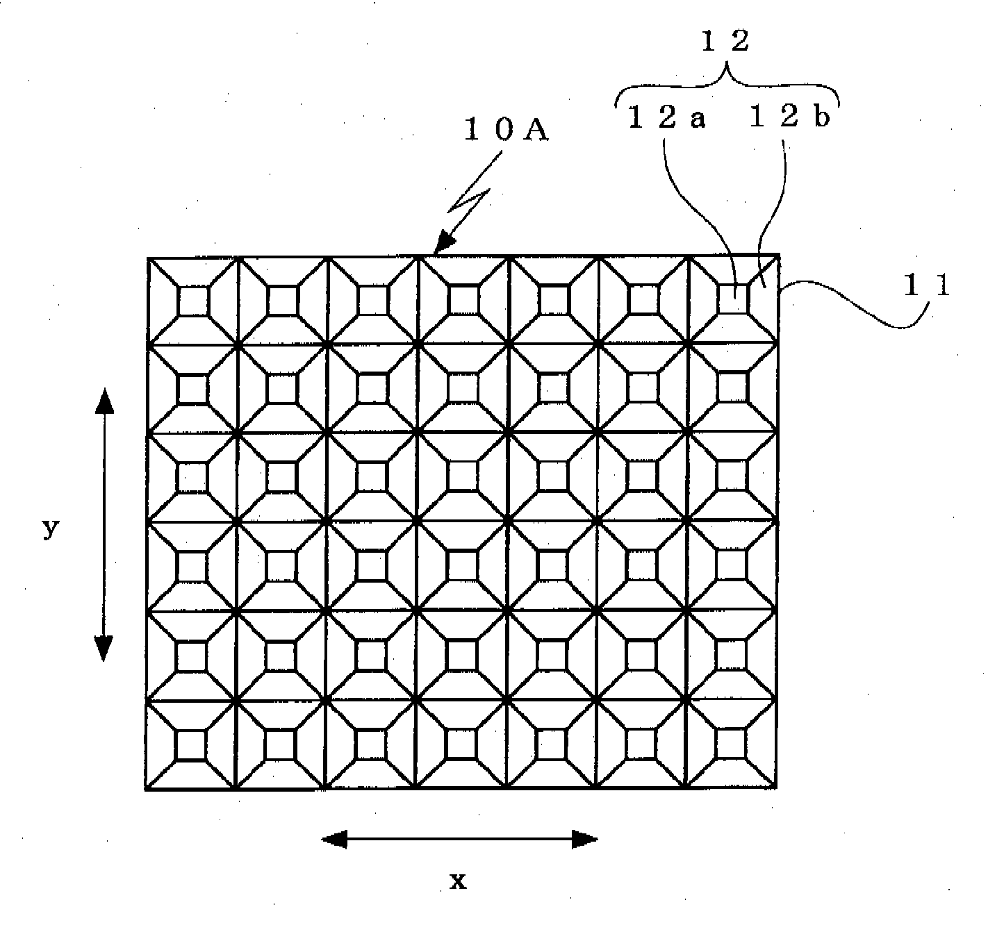
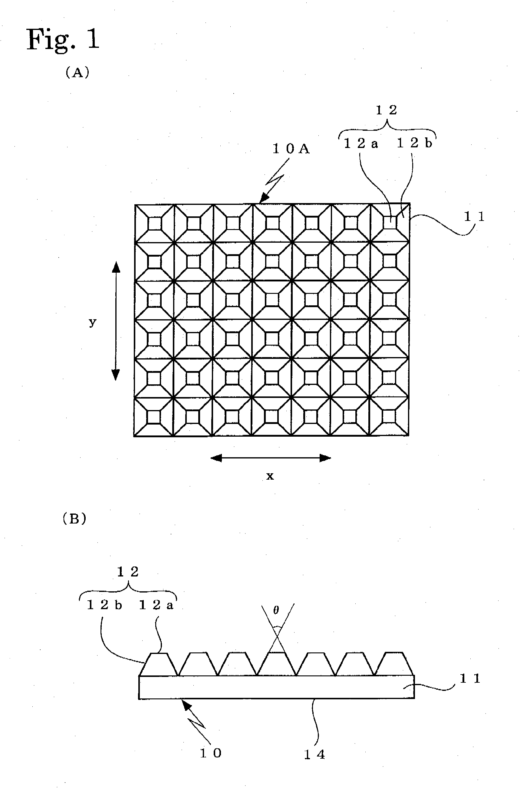
[0029]In a surface light emitter of an embodiment 1, a light control sheet 10A is used as a light control sheet 10. As shown in FIG. 1A and FIG. 1B, the light control sheet 10A has a configuration wherein projections 12 shaped like a truncated square pyramid and having square planar portions 12a at distal ends thereof are consecutively formed on one side of a transparent substrate 11 as arranged in x-direction and y-direction of the substrate 11. The projection 12 is configured such that the cross-sectional profiles thereof in the x-direction and in the y-direction of the transparent substrate 11 are the same isosceles trapezoid.

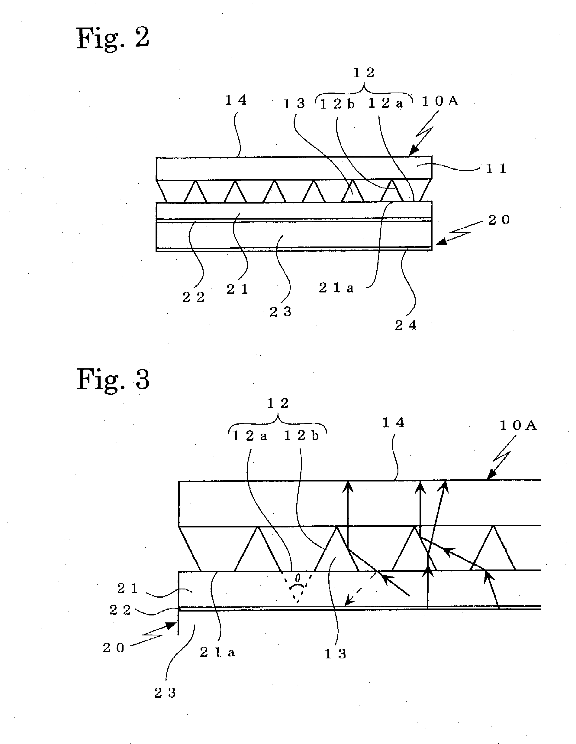
[0030]As shown in FIG. 2, the surface light emitter of the embodiment 1 employs a surface-emitting device 20 comprising an organic EL device wherein an organic EL layer 23 and a counter electrode 24 are overlaid on a surface of a transparent substrate 21, on which surface a transparent electrode 22 is overlaid. The planar portions 12a at the distal ends of t...

embodiment 2

[0041]In a surface light emitter of an embodiment 2, a light control sheet 10B is used as the light control sheet 10. As shown in FIG. 6A to FIG. 6C, the light control sheet has a configuration wherein the projections 12 shaped like a truncated rectangular pyramid and formed with rectangular planar portions 12a at the distal ends thereof are consecutively formed on the one side of the transparent substrate 11 as arranged in the x-direction and the y-direction thereof. The above projection 12 is configured such that the cross-sectional profiles thereof in the x-direction and in the y-direction of the transparent substrate 11 are isosceles trapezoids which have the same height but different shapes.

[0042]Similarly to the surface light emitter of the embodiment 1, the surface light emitter of the embodiment 2 is also assembled such that the planar portions 12a at the distal ends of the truncated-pyramid shaped projections 12 of the above light control sheet 10B are optically bonded to t...

embodiment 3

[0049]In a surface light emitter of an embodiment 3, a light control sheet 10C is used as the light control sheet. As shown in FIG. 8A to FIG. 8C, the light control sheet has a configuration wherein the projections 12 shaped like a truncated rectangular pyramid and formed with rectangular planar portions 12a at the distal ends thereof are consecutively formed on the one side of the transparent substrate 11 as arranged in the x-direction and the y-direction thereof. The above projection 12 is configured such that the cross-sectional profiles thereof in the x-direction and in the y-direction of the transparent substrate 11 are isosceles trapezoids which have different heights and shapes.

[0050]Similarly to the surface light emitter of the embodiment 1, the surface light emitter of the embodiment 3 is also assembled such that the planar portions 12a at the distal ends of the truncated-pyramid shaped projections 12 of the above light control sheet 10C are optically bonded to the output s...


PUM


Abstract

A front luminance of light emitted from a surface light emitting apparatus having a surface light emitting element is greatly improved. The surface light emitting apparatus is provided with a surface light emitting element (20) and a photochromic sheet (10). A repeated uneven pattern having a cross section in a trapezoidal shape is arranged at least on one side of the photochromic sheet, a flat portion (12a) at the tip on the protruding side of the unevenness is adhered to an emitting surface (21a) of the surface light emitting element, and conditions of 0.75>D>4[(sin θ−1/n)2+0.034] are met, where, θ is an apex angle formed by facing inclined surfaces protruded in a trapezoidal shape of the photochromic sheet, n is a refractive index of the photochromic sheet, and D is a ratio of the length of the surface light emitting element at a portion adhered to the emitting surface to the length of at least one cycle of the unevenness in an arrangement direction.

Description

TECHNICAL FIELD[0001]The present invention relates to a surface light emitter comprising a surface-emitting device and adapted to achieve a notable increase in the front brightness of light emitted therefrom.BACKGROUND ARTS[0002]With the increased diversity of IT devices and the like, recent years have seen increasing needs for compact surface-emitting devices consuming less power. As one of such surface-emitting devices, an electroluminescent device (hereinafter, abbreviated as EL device) is drawing attention.[0003]Such EL devices are generally classified into an inorganic EL device and an organic EL device by the material used therein.[0004]The inorganic EL device is generally adapted to emit light as follows. A high electric field is applied to a luminous portion whereby electrons are accelerated in the high electric field to impinge upon a luminescence center, which is excited to emit light. On the other hand, the organic EL device is adapted to emit light as follows. Electrons ...

Claims


Application Information

Patent Timeline
Patent Type & Authority Applications(United States)
IPC IPC(8): F21V11/06
CPCG02B5/045G02F2001/133607G02F1/133606G02B5/23G02F1/133607
Inventor KUISEKO, MANAMISATO, AKIRA
Owner MERCK PATENT GMBH
Why Eureka
Try Eureka