Collapsible Valve

a valve and collapsible technology, applied in the field of valves, can solve the problems of difficult swabbing and health problems of patients, and achieve the effect of less forward fall of the top portion

Active Publication Date: 2011-02-03
CAREFUSION 303 INC
View PDF5 Cites 124 Cited by
  • Summary
  • Abstract
  • Description
  • Claims
  • Application Information

AI Technical Summary

Problems solved by technology

Blood that is left in a catheter lumen may clot and cause health problems for the patient.
By contrast, many devices on the market use plastic valves that cannot flex to move out of the way to allow flow, thus requiring the use of valves that are slanted or incorporating features at the top, making swabbing difficult.

Method used


Image

  • Collapsible Valve
  • Collapsible Valve
  • Collapsible Valve

Examples


Embodiment Construction

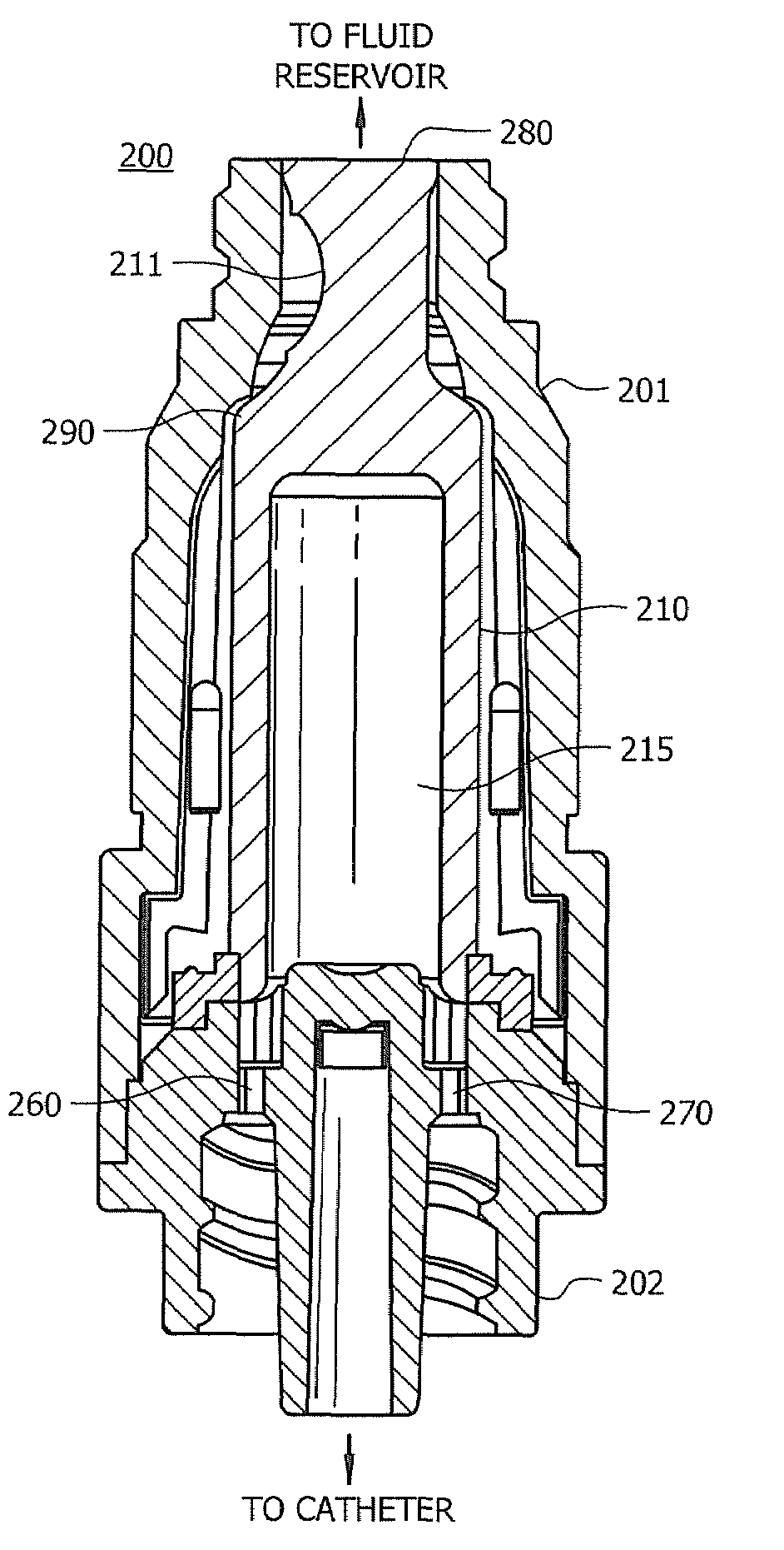
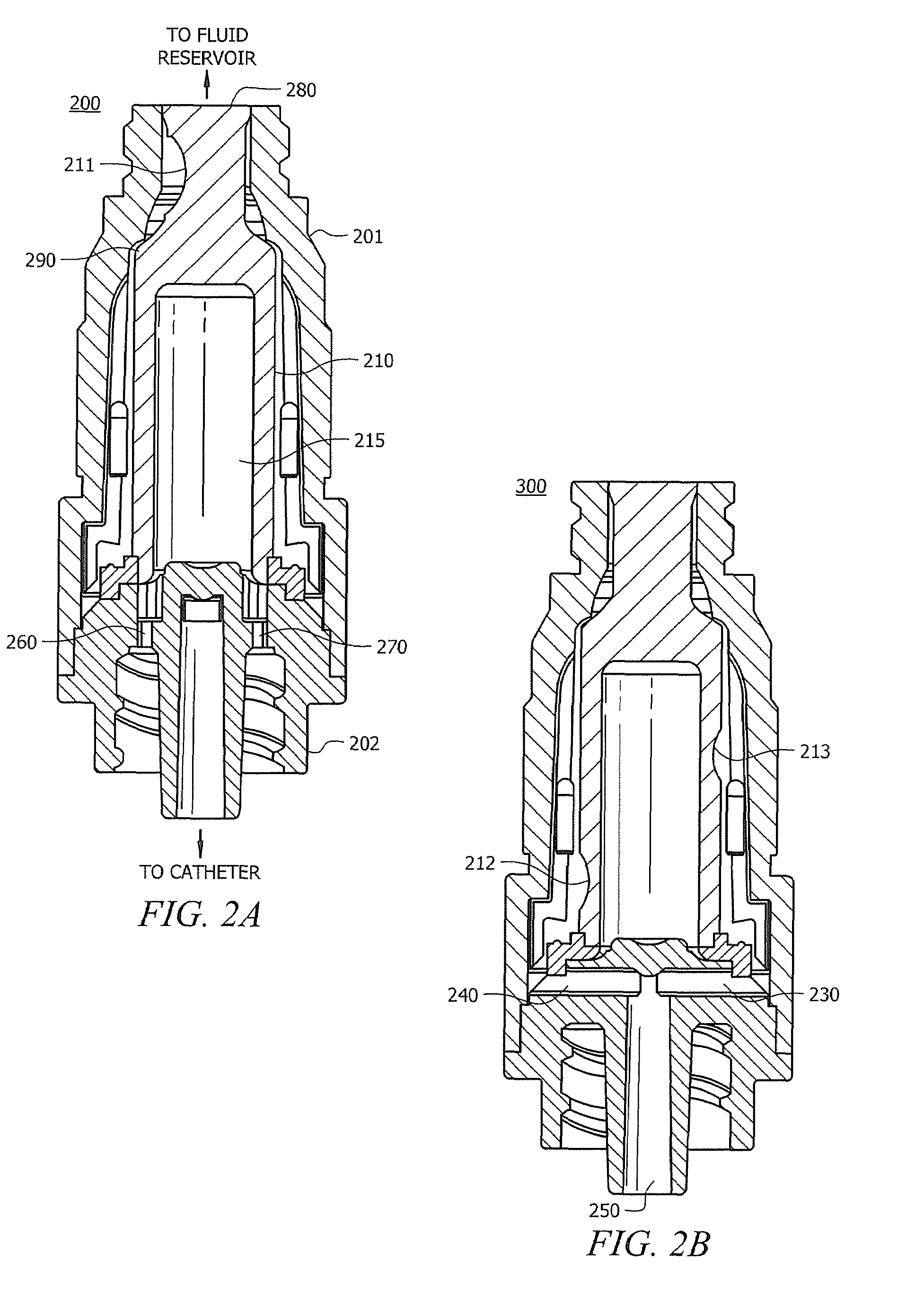
[0018]FIGS. 2A and 2B are cut-away views showing exemplary needleless access device 200 adapted according to one embodiment of the invention. The view in FIG. 2B is rotated ninety degrees from that shown in FIG. 2A.

[0019]Device 200 includes female luer fitting 201, male luer fitting 202, and valve 210. Valve 210 includes cut 211, which in this example, is referred to as a “smiley cut.” Valve 210 also includes dimples 212 and 213 on the outside of its lower portion and placed with axial and angular offsets from each other so that the body of valve 210 is not symmetrical. While cut 211 is referred to as a cut, it can be manufactured using any of a variety of techniques, including molding so that a cut is not actually made. An example of a material that may be used for male and female luer fittings 201 and 202 is polycarbonate, and an example of a material that may be used for valve 210 is silicone, though any of a variety of suitable materials may also be used in various embodiments.

[...


PUM

PropertyMeasurementUnit
thicknessaaaaaaaaaa
thicknessaaaaaaaaaa
lengthaaaaaaaaaa

Abstract

A collapsible valve comprising a first portion with at least one dimple in a side thereof, and a second portion, the second portion being narrower than the first portion and arranged along an axial dimension of the first portion, the second portion including a cut therein.

Description

TECHNICAL FIELD[0001]The present disclosure relates, generally, to fluid flow devices and, more specifically, to valves for use in medical devices.BACKGROUND OF THE INVENTION[0002]Needleless access devices allow a healthcare professional to, e.g., replace / add IV bags, and / or access an IV line without having to use a needle. FIG. 1 is a cut-away view of a current needleless access device 100. Needleless access device 100 includes female luer fitting 101, male luer fitting 102, and valve 103. When in use, male luer fitting 102 is connected to, e.g., a catheter or to a female luer, and female luer fitting 101 is connected to a fluid reservoir. Female luer fitting 101 is connected to the fluid reservoir via a second male luer fitting (not shown) that includes a hollow member inserted through the top of female luer fitting 101, collapsing valve 103 down into volume 104 to break the seal and create a fluid flow path. The hollow member of the second male luer fitting delivers the fluid, wh...

Claims


Application Information

Patent Timeline
Patent Type & Authority Applications(United States)
IPC IPC(8): A61M39/22B23P11/00B65B55/00
CPCA61M39/24A61M39/26A61M2207/00Y10T29/49826Y10T29/49405A61M39/22A61M39/10A61M2039/2433A61M2039/263A61M2039/266
Inventor MANSOUR, GEORGE M.BENNETT, JAMES
Owner CAREFUSION 303 INC
Why Eureka
Try Eureka