
Biting insect trap

a technology for insects and traps, applied in the field of insect traps, can solve the problems of ineffective devices utilizing ultraviolet light sources, ineffective attracting biting insects such as mosquitoes and flies, and preying on humans and livestock, and prior art devices utilizing pheromones as odor sources to attract specific types of insects are expensiv

Inactive Publication Date: 2011-02-10
BIOSENSORY INC +1
View PDF10 Cites 17 Cited by
  • Summary
  • Abstract
  • Description
  • Claims
  • Application Information

AI Technical Summary

Benefits of technology

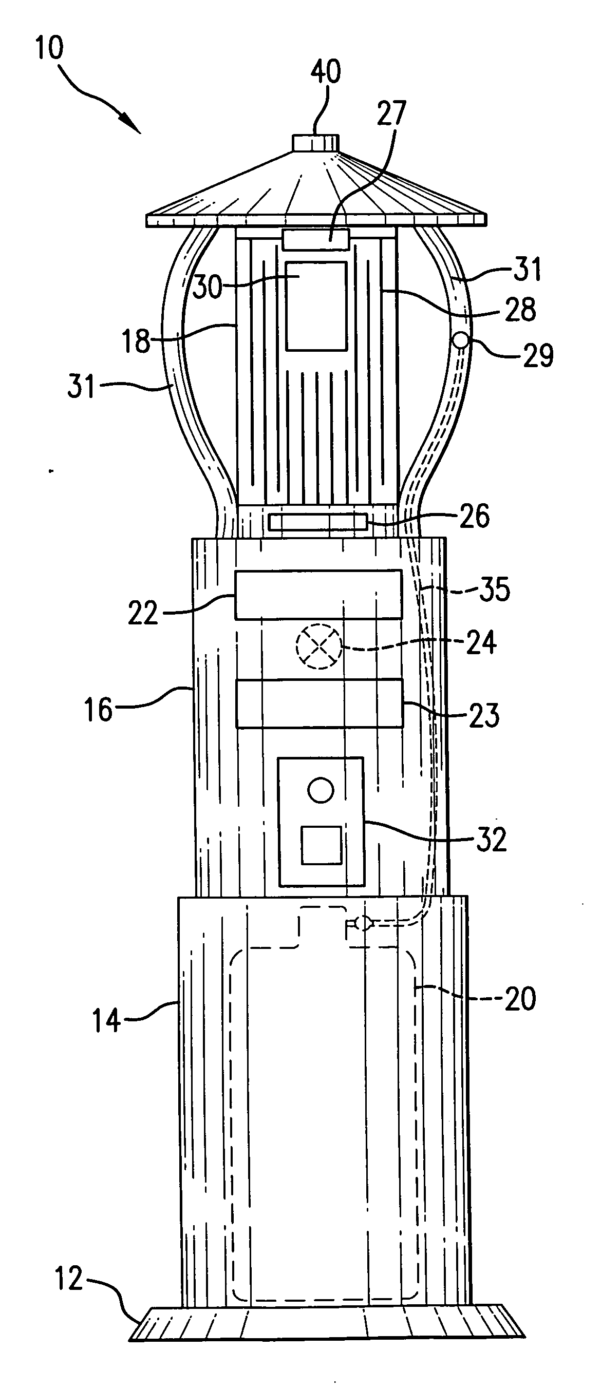
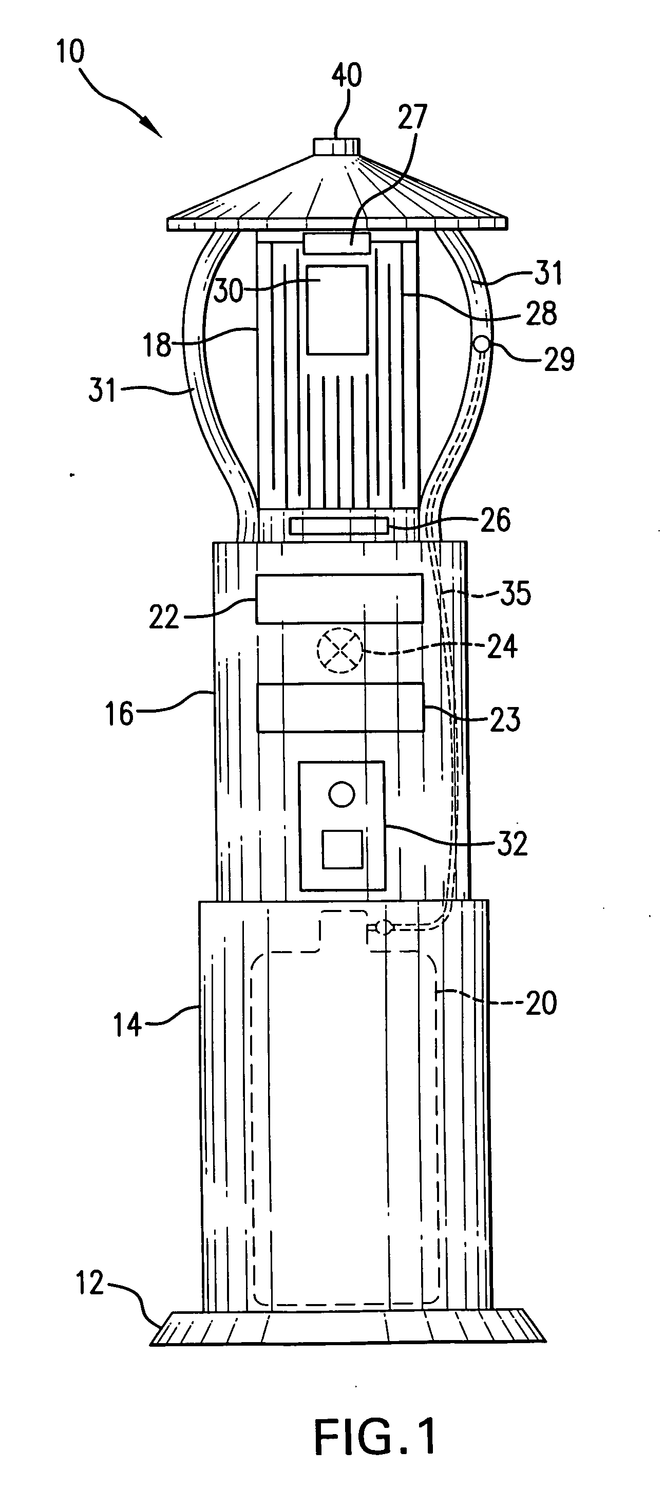
The present invention is a biting insect trap that attracts and traps biting insects using a heating element and a source of carbon dioxide. The heating element is designed to mimic the pattern of veins and arteries in the body of the insect. The trap has a base, lower housing with a carbon dioxide source, central housing with an induction fan, a fan discharge port, and an insect collection tray, and upper housing with a heating source and one or more insect capture ports. The invention is controlled by a controller on the central housing that regulates the emission of carbon dioxide from the emitter. The technical effect of this invention is to provide an effective and efficient tool for trapping biting insects in a safe and effective way.

Problems solved by technology

For example, the devices employing an ultraviolet light source are effective for attracting and destroying beneficial insects but are ineffective for attracting biting insects, such as mosquitoes and flies, that prey on humans and livestock.
The prior art devices which utilize pheromones as the odor source to attract specific types of insects are expensive because the pheromone source is continuously active and therefore must constantly be replaced.
However, the burning of propane can be dangerous in many instances, particularly in dry environments or where children are present.

Method used


Image

  • Biting insect trap
  • Biting insect trap

Examples


Embodiment Construction

[0012]As indicated above, the present invention is a biting insect trap for attracting and eliminating flying biting insects that is safe and does not employ grids with high electric current or burning flammable materials. The present inventors have developed a trap for biting insects that includes, among other things, a source of carbon dioxide, a heating element that mimics the arteries and veins of a mammal, and one or more chemical attractants. The carbon dioxide, heating element, and chemical attractants work in concert to attract flying biting insects such as mosquitoes and other pests. Moreover, the present invention collects these flying biting insects by sucking them into a collection vessel with the aid of an induction fan. This feature offers advantages over electrified grids or the burning of propane utilized in devices in the prior art in terms of safety and economy.

[0013]Accordingly, the present invention is directed to a biting insect trap, comprising a base; a lower ...


PUM


Abstract

The present invention is directed to a biting insect trap, comprising a base; a lower housing attached to the base and including a source of carbon dioxide disposed within the lower housing; a central housing attached to the lower housing and comprising, an induction fan, a fan discharge port, and an insect collection tray; an upper housing attached to the central housing and comprising a heating source disposed around the upper housing portion, the heating source having a heating element arranged in a pattern resembling veins and arteries; one or more insect capture ports, and an emitter disposed to emit carbon dioxide; a source of insect attractant disposed adjacent the heating element, such that the insect attractant is heated by the heating element; and a control panel comprising a controller positioned on the central housing, the controller controlling all the electronic functions of the device, as well as operation of the emitter so as to control emission of the carbon dioxide.

Description

CROSS-REFERENCE TO RELATED APPLICATIONS[0001]This application claims the benefit of U.S. Provisional Application Ser. No. 61 / 208,817 filed Feb. 27, 2009.BACKGROUND OF THE INVENTION[0002]1. Field of the Invention[0003]The present invention relates generally to apparatuses for attracting and destroying insects, and more particularly to an apparatus having a plurality of capture ports, a heating element, a chemical attractant, and an induction fan, and a controller which work in concert to effectively capture and destroy insects.[0004]2. Brief Description of the Related Art[0005]Devices for attracting and destroying insects are well-known in the art. For example, U.S. Pat. No. 2,106,528 to Jones et al., U.S. Pat. No. 3,187,458 to Densmore, U.S. Pat. No. 3,835,577 to Soulos, U.S. Pat. No. 3,894,351 to Iannini, U.S. Pat. No. 4,182,069 to DeYoreo, and U.S. Pat. No. 4,387,529 to Hedstrom are representative of the available prior art devices used to attract and destroy insects. The patent t...

Claims


Application Information

Patent Timeline
Patent Type & Authority Applications(United States)
IPC IPC(8): A01M1/08A01M1/10
CPCA01M1/023A01M2200/012A01M1/06
Inventor NOLEN, JAMES A.NELSON, ROBERT G.KLINE, DANIEL L.
Owner BIOSENSORY INC
Learn More