Display device, display method and computer program

Inactive Publication Date: 2011-02-17
SONY CORP
View PDF2 Cites 30 Cited by
  • Summary
  • Abstract
  • Description
  • Claims
  • Application Information

AI Technical Summary

Benefits of technology

[0020]According to the embodiments of the present invention described above, it is possible to provide a novel and improved display device, display method and computer program that are capable of suppressing occurrence of flick

Problems solved by technology

However, if the settings of the two cameras are different and differences in luminance and color are generated between the captured two types of images, flicker appears on the display device that causes the viewer to perceive a three-dimensional image using a system that alternately displays the left and right images.
As a result, adverse effects are generated, such as

Method used


Image

  • Display device, display method and computer program
  • Display device, display method and computer program
  • Display device, display method and computer program

Examples


Embodiment Construction

)

[0030]Hereinafter, preferred embodiments of the present invention will be described in detail with reference to the appended drawings. Note that, in this specification and the appended drawings, structural elements that have substantially the same function and structure are denoted with the same reference numerals, and repeated explanation of these structural elements is omitted.

[0031]An explanation will be given in the following order.

[0032]1. Embodiment of present invention

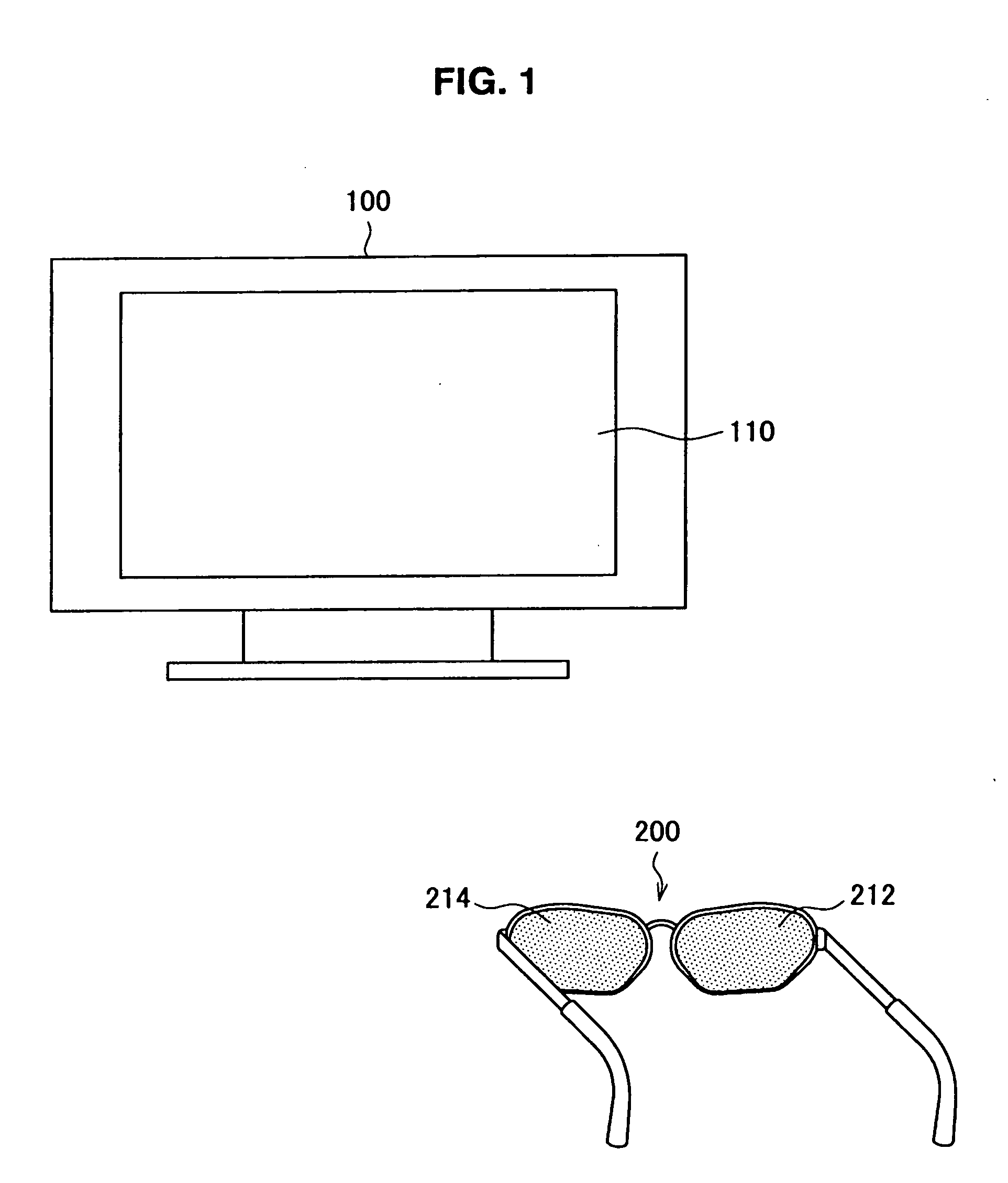
[0033]1-1. Structure of display device according to embodiment of present invention

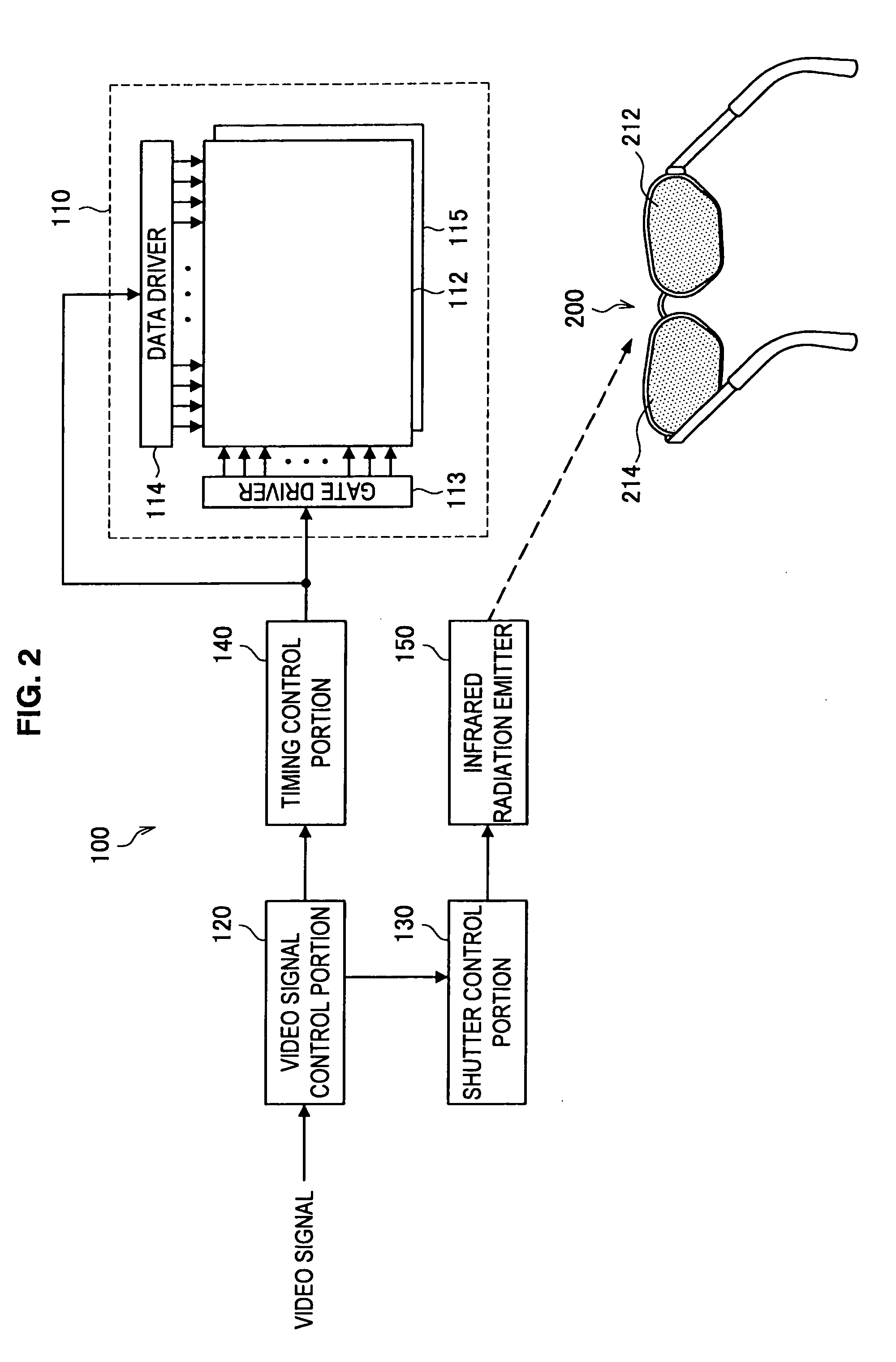
[0034]1-2. Functional structure of display device according to embodiment of present invention

[0035]1-3. Structure of video signal control portion

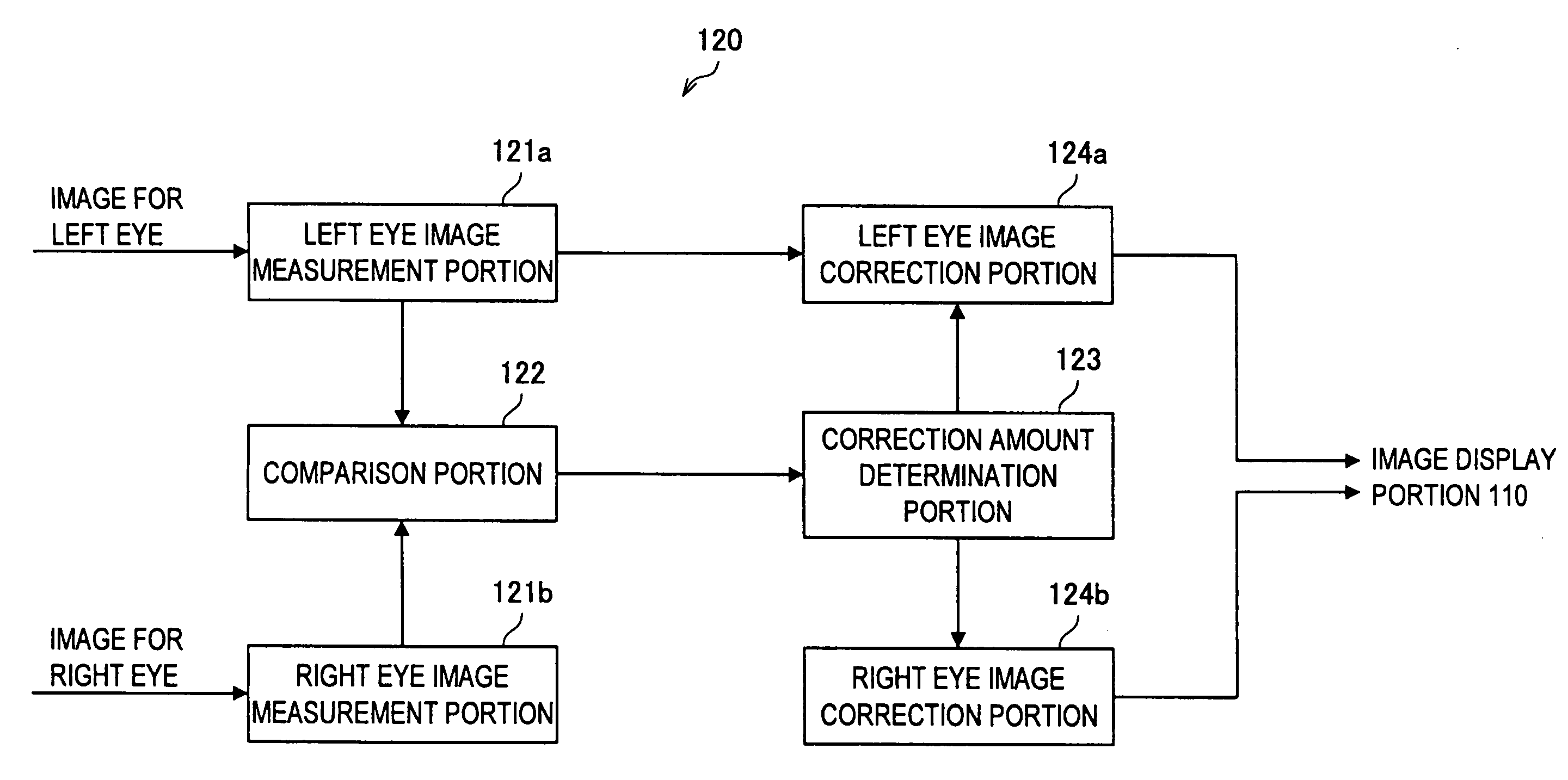
[0036]1-4. Structure of comparison portion

[0037]1-5. Method of image correction

[0038]2. Modified example of embodiment of present invention

[0039]2-1. Structure of video signal control portion

[0040]2-2. Method of image correction

[0041]3. Conclusion

1. Embodiment of Present Invention

1-1. S...


PUM


Abstract

There is provided a display device including a first measurement portion that measures information relating to luminance of a first image signal, and outputs a first measurement result, a second measurement portion that measures information relating to luminance of a second image signal, and outputs a second measurement result, a comparison portion that compares the first measurement result with the second measurement result and outputs differential data, a correction amount determination portion that determines, based on the differential data, a correction amount for at least one of the first image signal and the second image signal and a correction portion that corrects, based on the correction amount, the luminance of at least one of the first image signal and the second image signal.

Description

CROSS-REFERENCE TO RELATED APPLICATION[0001]The present application claims priority from Japanese Patent Application No. JP 2009-186789 filed in the Japanese Patent Office on Aug. 11, 2009, the entire content of which is incorporated herein by reference.BACKGROUND OF THE INVENTION[0002]1. Field of the Invention[0003]The present invention relates to a display device, a display method and a computer program.[0004]2. Description of the Related Art[0005]Display devices exist in which an image displayed on a screen is perceived by a viewer as a stereoscopic three-dimensional image. In order to cause the viewer to perceive the image as a stereoscopic three-dimensional image, it is necessary to display the image on the screen using a different display method than a normal display method. One example of such a display method is a technique in which the viewer is caused to perceive an image as a stereoscopic image by changing a polarization state of an image for the right eye and of an image...

Claims


Application Information

Patent Timeline
IPC IPC(8): H04N13/04
CPCH04N13/0025H04N13/0438H04N13/0037H04N13/0033H04N13/133H04N13/144H04N13/15H04N13/341
Inventor HATA, RYUHEI
Owner SONY CORP
Why Eureka
Try Eureka