Method and apparatus for insertion of an elongate pin into a surface

a technology of elongate pins and surfaces, applied in the field of apparatus for dictating the trajectory and location of insertion of elongate pins into surfaces, can solve the problems of obscured portions, surgeons may not be able to precisely determine the location of exposed areas relative to the rest,

Inactive Publication Date: 2011-02-17
THE CLEVELAND CLINIC FOUND
View PDF30 Cites 185 Cited by
  • Summary
  • Abstract
  • Description
  • Claims
  • Application Information

AI Technical Summary

Problems solved by technology

Depending upon the patient's particular anatomy, the surgeon may not be able to precisely determine the location of the exposed area relative to the remaining, obscured portions of the bone through mere visual observation.

Method used


Image

  • Method and apparatus for insertion of an elongate pin into a surface
  • Method and apparatus for insertion of an elongate pin into a surface
  • Method and apparatus for insertion of an elongate pin into a surface

Examples


Embodiment Construction

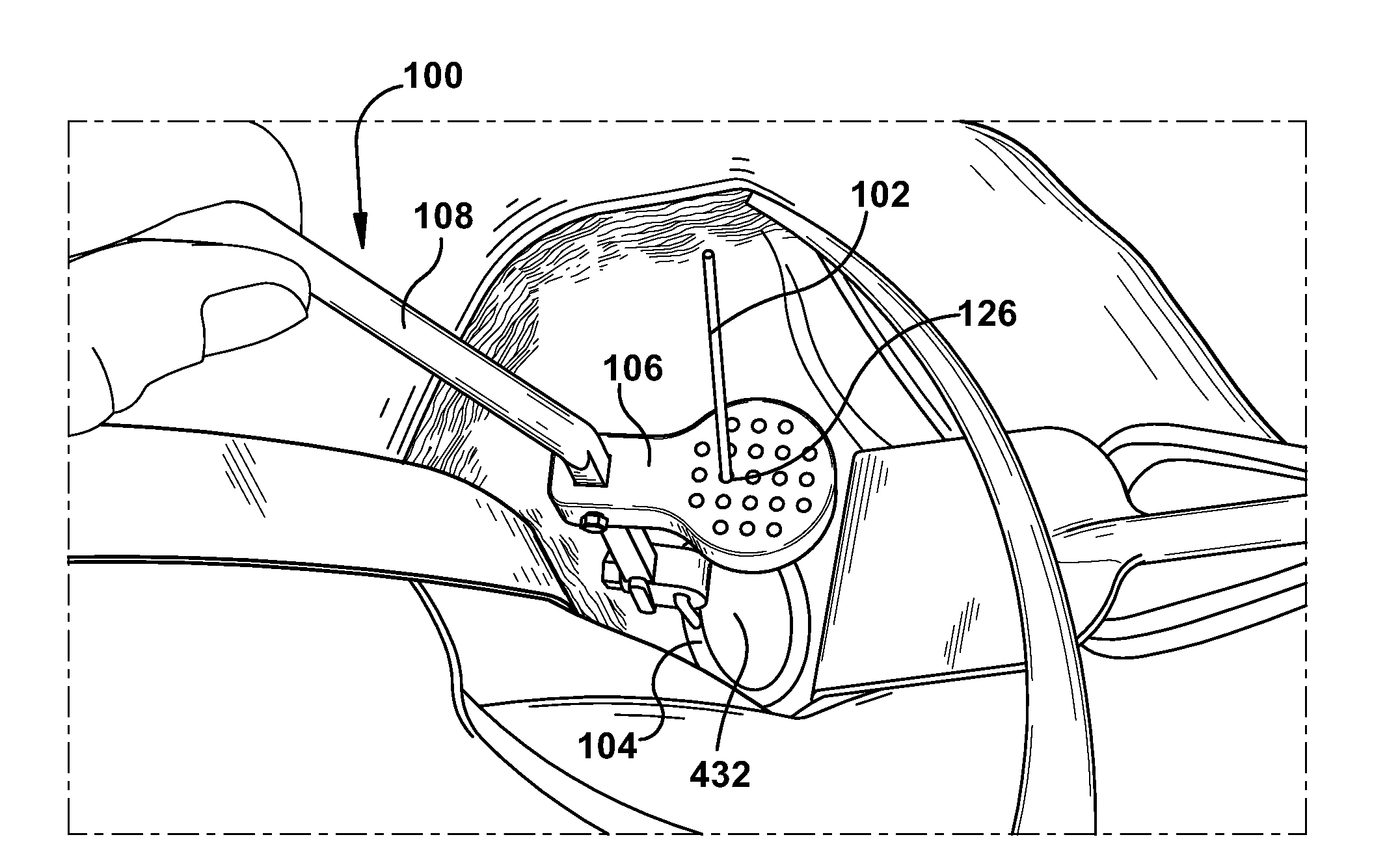
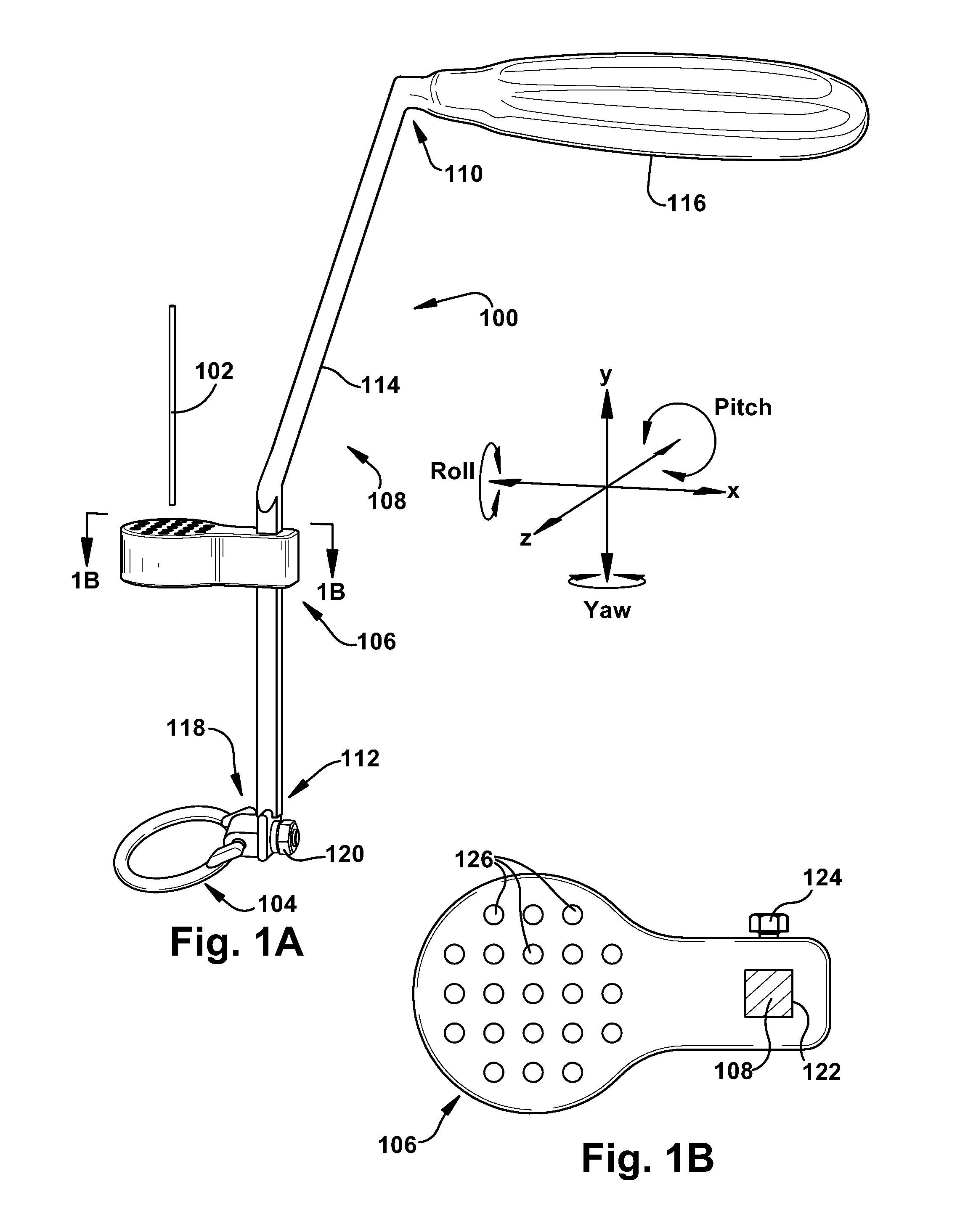
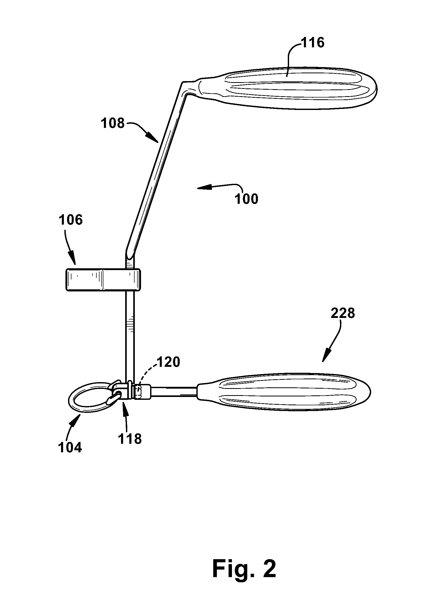
[0018]In accordance with the present invention, FIG. 1A depicts an apparatus 100, such as a guide pin positioning apparatus, for dictating trajectory and location for insertion of an elongate pin (schematically shown at 102) into a surface. The term “dictate” is defined herein as “requiring or determining necessarily”.

[0019]A trajectory structure 104 is configured for selective contact with the surface to dictate an insertion trajectory of the pin 102 relative to the surface. A location structure 106 is configured to allow longitudinal passage of at least a portion of the pin 102 therethrough to dictate an insertion location of the pin relative to the surface. At least a portion of each of the location structure 106 and the trajectory structure 104 may be at least one of a block, a ring, a paddle, a yoke, a saddle, a dome, and a dish. For example, the trajectory structure 104 shown in FIG. 1 A includes a ring-shaped portion, and the location structure 106 shown in FIG. 1A includes a...


PUM


Abstract

A trajectory structure is configured for contact with a surface to dictate an insertion trajectory of a pin relative to the surface. A location structure is configured to allow longitudinal passage of at least a portion of the pin therethrough to dictate an insertion location of the pin relative to the surface. An elongate handling rod is connected to the trajectory structure and the location structure. The handling rod supports the trajectory structure and the location structure for manipulation by a user. The handling rod spaces the trajectory structure and the location structure longitudinally apart. The trajectory structure is connected to the handling rod for trajectory adjustment in at least two degrees of freedom relative to the handling rod. The insertion trajectory of the pin insertion is substantially dependent upon the trajectory adjustment. A method for inserting an elongate guide pin into a bone surface is also provided.

Description

RELATED APPLICATION[0001]This application claims priority from U.S. Provisional Application No. 61 / 232,842, filed Aug. 11, 2009, the subject matter of which is incorporated herein by reference.TECHNICAL FIELD[0002]The present invention relates to an apparatus and method for use of an insertion tool and, more particularly, to an apparatus for dictating trajectory and location for insertion of an elongate pin into a surface.BACKGROUND OF THE INVENTION[0003]In the installation of a prosthetic shoulder joint into a patient's body, a glenoid component is implanted into the glenoid vault of the patient's scapula. An obverse surface of the glenoid component is configured for articulating contact with a humeral component carried by the patient's humerus. A reverse surface of the glenoid component is secured to the bone surface of the glenoid vault.[0004]Because the shoulder prosthesis is normally provided to correct a congenital or acquired defect of the native shoulder joint, the glenoid v...

Claims


Application Information

Patent Timeline
Patent Type & Authority Applications(United States)
IPC IPC(8): A61B17/56
CPCA61B17/1739A61B2017/1778A61B2017/90A61B17/8897A61B17/1778A61B17/90
Inventor IANNOTTI, JOSEPH P.
Owner THE CLEVELAND CLINIC FOUND
Why Eureka
Try Eureka