Flow control valve

Inactive Publication Date: 2011-02-24
LEANVENT
View PDF11 Cites 7 Cited by
  • Summary
  • Abstract
  • Description
  • Claims
  • Application Information

AI Technical Summary

Benefits of technology

[0007]It is an object of preferred embodiments of the present invention to provide a valve system, which overcomes or reduces some of the above drawbacks of state-of-the art systems. Specifically, it is an object of preferred embodiments of the invention to provide a flow control valve which is easy to install. It is a further object of pre

Problems solved by technology

Most of such valves do, however, result in a relatively large flow resistance, i.e. energy loss, as well as unsatisfactory generation of aerodynamic noise as a consequence of sharp edges provided by the valve plates.
Venturi valves are, however, relatively expensive, and their installation is complicated.
Such va

Method used


Image

  • Flow control valve
  • Flow control valve
  • Flow control valve

Examples


Example

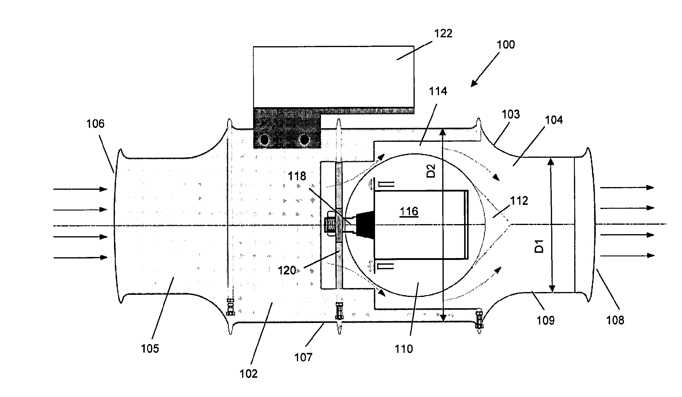
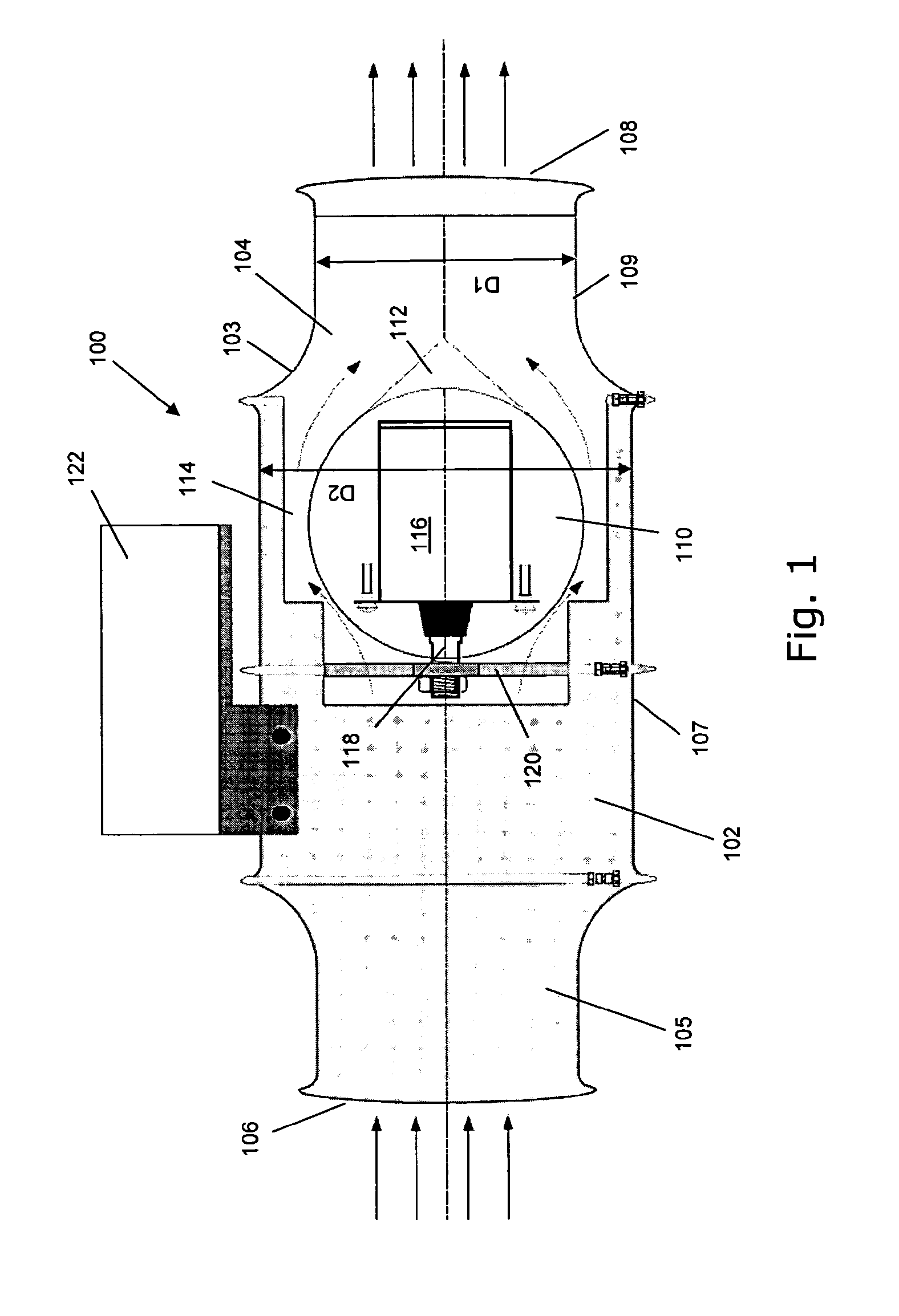
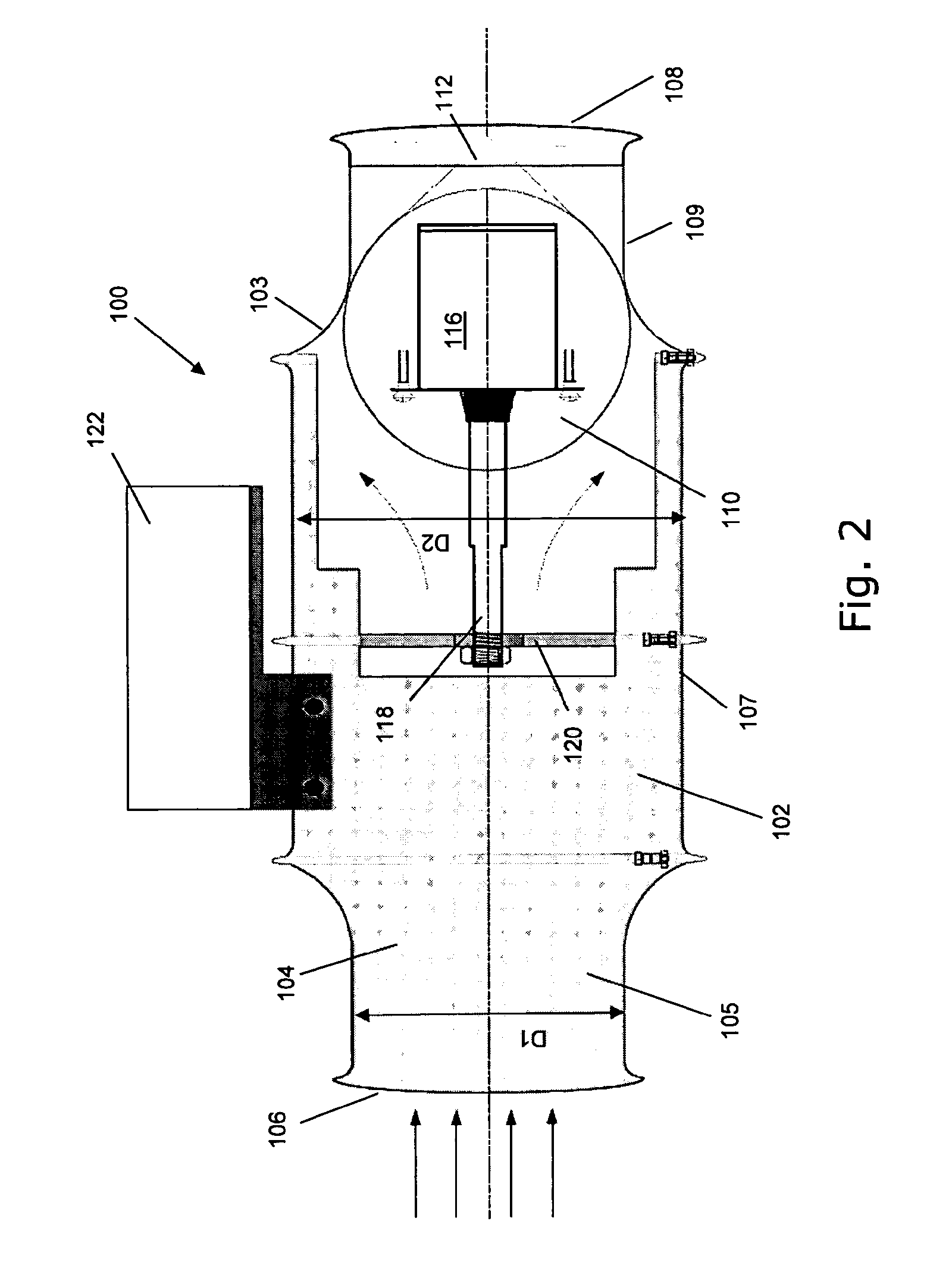
[0072]FIGS. 1 and 2 show an embodiment of a flow control valve 100 incorporating the inventions of the first, second and third aspects of the invention. FIG. 1 shows the valve in its fully open position, and FIG. 2 shows the valve in its fully closed position. The valve 100 has a housing 102 defining a flow passage 104, which extends between a flow inlet 106 and a flow outlet 108. The valve is suitable for attachment to respective end portions of pipe sections of a ventilation or exhaust duct. The valve 100 further comprises a spherical closing element 110, which at its downstream face is extended by a conical element 112 for improving the aerodynamical properties, i.e. for minimizing or eliminating the risk of flow separation. In FIG. 1, the valve is shown in its open position, wherein a clearance 114 is provided between the closing element 110 and an inner wall of the housing 102. As shown by arrows in FIG. 1, a fluid flow, such as flow of air or another gas, may flow from the inl...


PUM


Abstract

A flow control valve (100;200;300) for a ventilation or exhaust duct comprises a housing (102;202;302), which defines a longitudinally extending passage (104;204;304) between a flow inlet and a flow outlet. A closing element (110;210;310) in the passage is movable between a fully open position and a fully closed position. A motor or actuator (116;216;316) is provided for moving the closing element. The motor or actuator may be located inside the closing element (110;210;310). The flow passage (104;204;304) through the housing may have sections of different diameters to obtain a venturi-like diffusor. A pressure difference sensor may be provided, which in combination with a position of the closing element allows for computation of the flow rate through the valve without the need for a separate flow meter.

Description

TECHNICAL FIELD[0001]The present invention relates to valve systems for controlling the flow of fluids, such as air and gasses, in ducts and pipe systems, particularly ventilation and exhaust ducts. The valve systems are primarily aimed at controlling flow rates.BACKGROUND OF THE INVENTION[0002]One type of state-of-the art flow control valves, in particular air control valves for ventilation ducts, typically comprises a valve plate which is arranged in the flow duct in such a way that the plate is rotatable around an axis which extends transversely to the fluid flow direction through the duct and valve. For applications requiring accurate flow control, so-called iris valves are sometimes applied, which are typically designed on the basis of a plurality of mutually displaceable plates, whereby, depending on the position of the plates, a clearance of a variable size is provided for the fluid flow. In respect of relatively large ducts, louvre valves are often used, which include a plur...

Claims


Application Information

Patent Timeline
IPC IPC(8): F15D1/00F16K31/02F16L9/22F16L55/10
CPCF16K1/12F16K1/126F16K37/0041F16K37/0083F16K37/0091Y10T137/7761Y10T137/0318Y10T137/3476
Inventor ANTONSEN, PETER S.
Owner LEANVENT
Why Eureka
Try Eureka