
Eureka
For R&D, Eureka makes reading and utilizing patents & technical documents easy.
Eureka AIR
Designed for self-driven R&D workflows. Generate viable solutions, solve complex R&D challenges, empower your innovation with AI.

Eureka Materials
Designed for material experts only. Revolutionize your material R&D, from search, analyze, to developing new materials.

TechResearch
Generate reliable direction feasibility study reports for your R&D in just a few steps.

TechSeek
Discover and master advanced knowledge NOW. Basics, ideas, possibilities, all at once.

TechMind
As an expert in R&D Theories, TechMind can generates customized viable solutions instantly.

TechRisk
Analyze your overall solution with one click, know your potential R&D risks in advance.

TechMonitor
Get weekly tech updates, stay abreast of the latest tech innovations and key insights.
Internal combustion engine control apparatus, and internal combustion engine control method
- Summary
- Abstract
- Description
- Claims
- Application Information
AI Technical Summary
Benefits of technology
Problems solved by technology
Method used
Image

Examples
embodiment 1
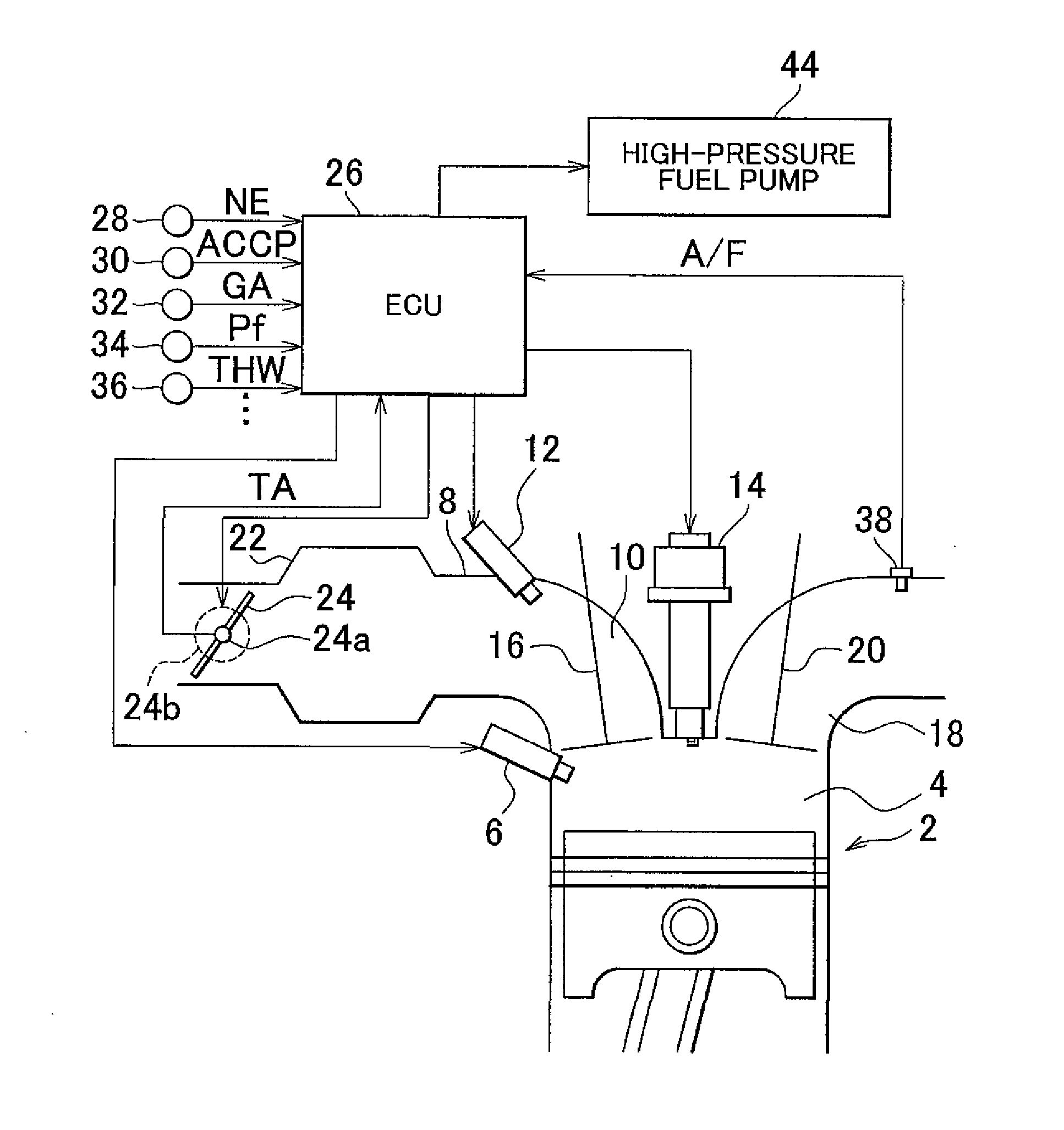
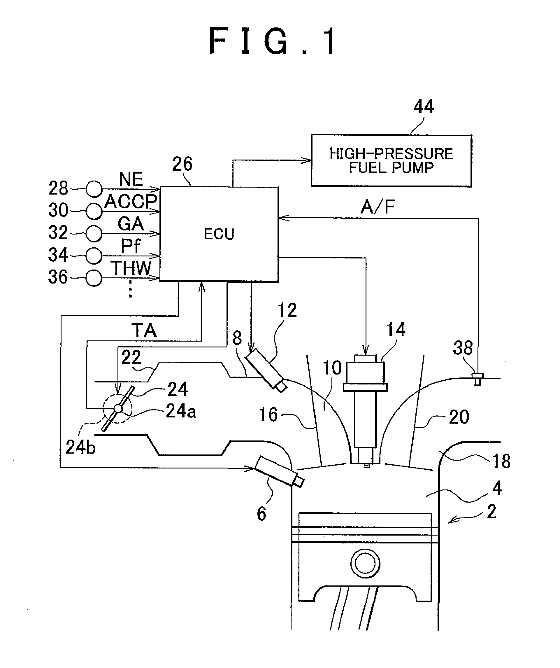
[0070]FIG. 1 is a block diagram representing a general construction of an internal combustion engine 2 and an internal combustion engine control apparatus to which the invention is applied. The internal combustion engine 2 is an internal combustion engine for a vehicle. This engine 2 is provided with in-cylinder-injecting fuel injection valves 6 (corresponding to in-cylinder fuel injection means) that inject fuel into combustion chambers 4. An intake passageway 8 of the engine 2 is provided with intake port-injecting fuel injection valves 12 (corresponding to in-intake passageway fuel injection means) that inject fuel into intake gas in intake ports 10. Thus, the internal combustion engine 2 of this embodiment adopts a dual injection system. An ignition plug 14 that ignites by spark a mixture of fuel and air is provided on a top surface of each combustion chamber 4 of the internal combustion engine 2.
[0071]The combustion chambers 4 are provided with intake valves 16 that open and cl...
embodiment 2
[0097]In Embodiment 1 it is determined whether or not Fdio≧Fmin in step S112 in the fuel injection allotment control process (FIG. 4), whereas in Embodiment 2 it is determined whether or not Fdio≧Fmin×Kf, or whether or not Fdio≧min+dF.
[0098]Herein, the coefficient Kf is a value as an increasing coefficient above 1; for example, the coefficient Kf is “1.1” or the like. The additional value dF represents a value for giving an increase corresponding to a marginal amount to the minimum fuel injection amount Fmin. Through the determination performed in this manner, it is possible to determine a state that occurs immediately before the minimum fuel injection amount Fmin exceeds the planned demanded in-cylinder injection amount Fdio.
[0099]Since the minimum fuel injection amount Fmin used is the largest value among representative values or actually measured values of the same kind of in-cylinder-injecting fuel injection valves 6, there exists an error between the minimum fuel injection amou...
embodiment 3
[0102]In this embodiment, a fuel injection allotment control process shown in FIG. 8 is executed in place of the fuel injection allotment control process (FIG. 4) of Embodiment 1, by an interrupt at every rotation of a constant crank angle. Other constructions are the same as in Embodiment 1.
[0103]When the fuel injection allotment control process (FIG. 8) starts, the high-pressure fuel pressure Pf, the intake gas amount GA and the engine rotation speed NE are firstly input (S202), and then calculation of the total demanded injection amount Ft (S204) and calculation of the in-cylinder injection allotment proportion Rf (S206) are executed. These steps S202 to S206 are the same processes as the steps S102, S106 and S108, respectively, in the fuel injection allotment control process (FIG. 4).
[0104]Next, on the basis of the “Ft×Rt” (g) that is the allotted fuel injection amount of the in-cylinder-injecting fuel injection valves 6, an injectable fuel pressure Pfmin (Pa) that is the highes...
PUM
 Abstract
Description
Claims
Application Information
 - R&D Engineer
- R&D Manager
- IP Professional
- Industry Leading Data Capabilities
- Powerful AI technology
- Patent DNA Extraction
Browse by: Latest US Patents, China's latest patents, Technical Efficacy Thesaurus, Application Domain, Technology Topic, Popular Technical Reports.
© 2024 PatSnap. All rights reserved.Legal|Privacy policy|Modern Slavery Act Transparency Statement|Sitemap|About US| Contact US: help@patsnap.com