Control device and control method for internal combustion engine

a control device and control method technology, applied in the direction of electrical control, machine/engine, exhaust treatment electric control, etc., can solve the problems of affecting the efficiency of the engine, the temperature of the filter may fall below, and the regeneration processing of the filter may not be appropriately executed, so as to achieve the effect of increasing the temperature increase

Active Publication Date: 2019-04-11
TOYOTA JIDOSHA KK
View PDF1 Cites 3 Cited by
  • Summary
  • Abstract
  • Description
  • Claims
  • Application Information

AI Technical Summary

Benefits of technology

[0012]In a case where an operation point that is determined by the rotation speed of the crankshaft of the internal combustion engine and the load of the internal combustion engine varies, even though the absolute value of the difference between the air-fuel ratio in the rich combustion cylinder and the air-fuel ratio in the lean combustion cylinder is the same, the temperature increase effect through the dither control processing may vary. For this reason, the difference between the air-fuel ratio in the rich combustion cylinder and the air-fuel ratio in the lean combustion cylinder is variably set according to the rotation speed of the crankshaft of the internal combustion engine and the load of the internal combustion engine, whereby it is possible to make the temperature increase effect of the dither control processing appropriate regardless of the operation point of the internal combustion engine.
[0013]In particular, in the first aspect of the disclosure, the difference is variably set using the map data for the first mode in the first mode, and the difference is variably set using the map data for the second mode in the second mode. For this reason, in comparison with a case where a value determined using the map data for the first mode is reduced at a predetermined reduction ratio with respect to the second mode, in regard to an operation point where the difference between the average value of the exhaust gas air-fuel ratios determined by the map data for the first mode and the lean-side misfire limit is large, it is possible to make the absolute value of the difference in the second mode large, thereby increasing the temperature increase effect.

Problems solved by technology

However, in a case where the temperature of the filter increases to the temperature range appropriate for the regeneration processing and the dither control processing itself is stopped, the temperature of the filter may fall below the temperature range appropriate for the regeneration processing, and the regeneration processing of the filter may not be appropriately executed.

Method used


Image

  • Control device and control method for internal combustion engine
  • Control device and control method for internal combustion engine
  • Control device and control method for internal combustion engine

Examples


Embodiment Construction

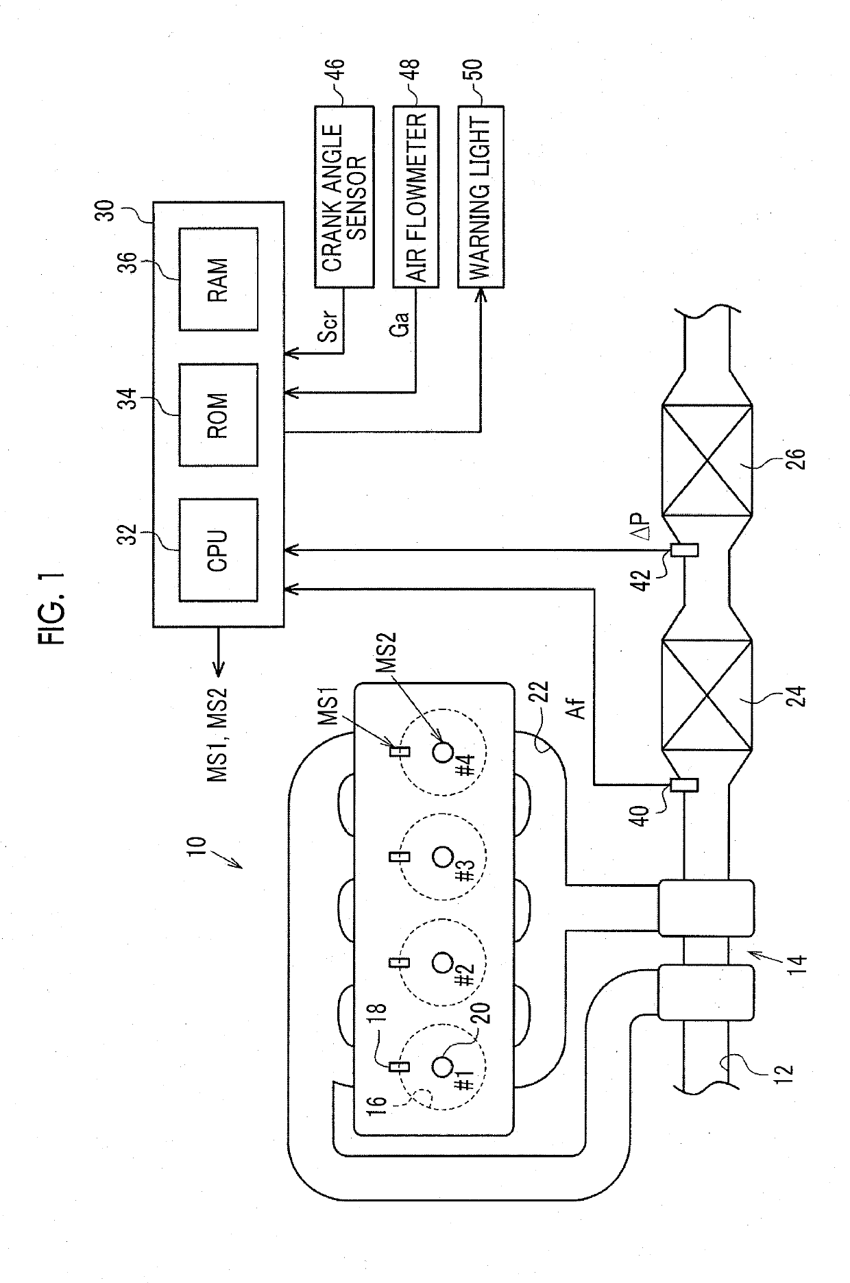
[0025]Hereinafter, an embodiment of a control device for an internal combustion engine will be described referring to the drawings. In an internal combustion engine 10 shown in FIG. 1, air sucked from an intake passage 12 flows into a combustion chamber 16 of each of cylinders #1 to 111 through a turbocharger 14. Each of the cylinders #1 to #4 is provided with a fuel injection valve 18 that injects fuel, and an ignition device 20 that causes spark discharge. In the combustion chamber 16, an air-fuel mixture of air and fuel is supplied for combustion, and the air-fuel mixture supplied for combustion is discharged as exhaust gas to an exhaust passage 22. In the exhaust passage 22 downstream of the turbocharger 14, a three-way catalyst 24 having oxygen storage ability is provided. In the exhaust passage 22 downstream of the three-way catalyst 24, a gasoline particulate filter (hereinafter, referred to as a “GPF”) 26 is provided.

[0026]An electronic control unit 30 adapts the internal co...


PUM


Abstract

A control device for an internal combustion engine includes an electronic control unit configured to execute dither control processing in a first mode and a second mode. The dither control processing is processing for operating a fuel injection valve such that an air-fuel ratio of at least one cylinder among cylinders becomes lean air-fuel ratio, and an air-fuel ratio of cylinders different from the at least one cylinder becomes rich air-fuel ratio when a condition that a regeneration request of the filter occurs is established. In the second mode, an absolute value of the difference between the air-fuel ratio in the lean combustion cylinder and the air-fuel ratio in the rich combustion cylinder smaller than in the first mode.

Description

INCORPORATION BY REFERENCE[0001]The disclosure of Japanese Patent Application No. 2017-196212 filed on Oct. 6, 2017 including the specification, drawings and abstract is incorporated herein by reference in its entirety.BACKGROUND1. Technical Field[0002]The present disclosure relates to a control device and a control method for an internal combustion engine including a plurality of cylinders, a filter configured to trap particulate matter in exhaust gas discharged from the cylinders, and a fuel injection valve provided in each of the cylinders.2. Description of Related Art[0003]For example, Japanese Unexamined Patent Application Publication No. 2009-36183 (JP 2009-36183 A) describes that a filter configured to trap particulate matter in exhaust gas is provided in an exhaust passage of an internal combustion engine. JP 2009-36183 A describes that the filter is set at a high temperature for regeneration processing of the filter for eliminating the particulate matter trapped on the filt...

Claims


Application Information

Patent Timeline
Patent Type & Authority Applications(United States)
IPC IPC(8): F02D41/02F02D41/24
CPCF02D41/029F02D41/2422F02D2200/0802F02D2200/101F02D2200/1002F02D41/024F02D41/1475F01N3/0253F01N9/002F01N2430/06F01N2560/025F01N2560/08F01N2900/0408F01N2900/08F01N2900/1402F01N2900/1602F01N2900/1606F02D41/0082F02D41/025F02D41/1408F02D41/1454Y02T10/12Y02T10/40F01N3/023F01N2560/06F02D41/14
Inventor AKUTSU, TOMOKAZUNAKAMURA, TAKASHIKOBASHI, NORIYASU
Owner TOYOTA JIDOSHA KK
Why Eureka
Try Eureka