Positioning structure of turn lamp assembly in outer mirror with turn lamp

a technology of turn lamps and assembly parts, which is applied in the direction of vehicle components, optical viewing, signalling/lighting devices, etc., can solve the problems of easy misalignment, and achieve the effects of preventing worsening appearance, accurate positioning, and easy insertion

Active Publication Date: 2011-03-03
MURAKAMI CORP
View PDF5 Cites 2 Cited by
  • Summary
  • Abstract
  • Description
  • Claims
  • Application Information

AI Technical Summary

Benefits of technology

[0008]The present invention provides a positioning structure of a turn lamp assembly in an outer mirror with turn lamp having a structure in which a turn lamp assembly is mounted to a mirror housing or a frame mounted to the mirror housing or the mirror housing and the frame, then a housing cover is placed over and mounted to the mirror housing, and a lens of the turn lamp assembly is exposed through an opening in the housing cover, including: a protrusion or a recess (or alternatively a hole) formed in a peripheral edge of the opening in a back surface of the housing cover; and a recess (or alternatively a hole) or a protrusion that is formed in the turn lamp assembly and engages the protrusion or the recess (or alternatively the hole) of the housing cover when the housing cover is placed over the mirror housing mounted with the turn lamp assembly. According to the present invention, the protrusion or the recess (or alternatively the hole) of the housing cover is inserted into and engaged with the recess (or alternatively the hole) or the protrusion of the turn lamp assembly when the housing cover is placed over the mirror housing, thereby preventing misalignment between the lens of the turn lamp assembly and the opening in the housing cover and preventing worsened appearance.
[0009]In the present invention, the recess (or alternatively the hole) or the protrusion of the turn lamp assembly may be formed in a position closer to a vehicle body than a securing position of the turn lamp assembly to the mirror housing or the frame or the mirror housing and the frame. This can prevent misalignment between the lens of the turn lamp assembly and the opening in the housing cover particularly in the position on the side close to the vehicle body.
[0010]In the present invention, the recess (or alternatively the hole) or the protrusion of the turn lamp assembly may be formed in a position on the side close to the vehicle body in a longitudinal direction of the turn lamp assembly (for example, a position closer to the vehicle body than a position at one half of the entire length in the longitudinal direction, or than a position at one third of the entire length in the longitudinal direction from the vehicle body side). In general, misalignment between the lens of the turn lamp assembly and the opening in the housing cover noticeably occurs in the position on the side close to the vehicle body in the longitudinal direction of the turn lamp assembly. In contrast, according to the configuration stated above, since the recess (or alternatively the hole) or the protrusion of the turn lamp assembly is formed in the position stated above, the misalignment between the lens and the opening in the housing cover in the position can be prevented. In particular, in an embodiment described later, the recess (or alternatively the hole) or the protrusion of the turn lamp assembly is formed as a protruding piece formed to protrude closer to the vehicle body than an end of the lens of the turn lamp assembly exposed on the side close to the vehicle body. In general, the misalignment between the lens of the turn lamp assembly and the opening in the housing cover particularly noticeably occurs in the end position of the lens of the turn lamp assembly exposed on the side close to the vehicle body. In contrast, according to the configuration stated above, since the recess (or alternatively the hole) or the protrusion of the turn lamp assembly is formed in the position closer to the vehicle body than the end position of the lens of the lamp assembly, the end position of the lens exposed on the side close to the vehicle body can be accurately positioned and therefore the misalignment between the lens and the opening in the housing cover in the end position can be prevented.
[0011]In the present invention, the protrusion may be tapered so as to be easily inserted into the facing recess or the facing hole. In the present invention, for example, the protrusion may be constituted by a front cross-shaped rib, and the recess or the hole may be formed into a rectangular shape into which the rib fits. According to this, engagement between the front cross-shaped rib and the recess or the hole allows the lens of the turn lamp assembly and the opening in the housing cover to be positioned both vertically and laterally.

Problems solved by technology

Thus, with the housing cover (5) being placed over and mounted to the mirror housing (4), alignment between an opening end (innermost part of the opening) (a position on the side close to a vehicle body) of the housing cover (5) and the lens (12) of the turn lamp assembly is difficult, and therefore misalignment easily occurs therebetween when the housing cover is distorted.

Method used


Image

  • Positioning structure of turn lamp assembly in outer mirror with turn lamp
  • Positioning structure of turn lamp assembly in outer mirror with turn lamp
  • Positioning structure of turn lamp assembly in outer mirror with turn lamp

Examples


Embodiment Construction

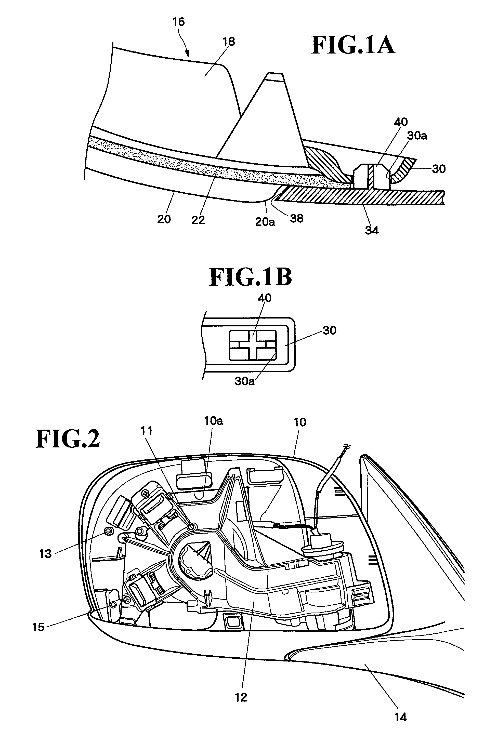
[0022]An embodiment of the present invention will be described below. FIG. 2 shows a vehicle right side door mirror according to the present invention viewed from a back side of the door mirror with a turn lamp assembly and a housing cover being removed. A frame 12 made of metal or rigid plastic is removably mounted to a back surface of a plastic mirror housing 10 by threading screws from a front side of the mirror housing 10. On the frame 12 and the mirror housing 10, bosses 11, 13 and 15 are formed for supporting and securing a turn lamp assembly (described later). The boss 11 is formed on the frame 12 and the bosses 13 and 15 are formed on the mirror housing 10. Screw holes are formed in top surfaces of the bosses 11, 13 and 15, respectively. A front surface (not shown) of the frame 12 is exposed through an opening 10a formed at a center of the mirror housing 10 to the front side of the mirror housing 10. To the exposed front surface of the frame 12, a mirror surface angle adjust...


PUM


Abstract

In an outer mirror with turn lamp having a structure in which a turn lamp assembly is mounted to a mirror housing, then a housing cover is placed over and mounted to the mirror housing, and a lens of the turn lamp assembly is exposed through an opening in the housing cover, misalignment between the lens of the turn lamp assembly and the opening in the housing cover is prevented. A protrusion is formed on a back surface near the innermost part of an opening in a housing cover. A hole is formed in the turn lamp assembly in a position facing the protrusion with the housing cover being placed over the mirror housing. When the housing cover is placed over the mirror housing, the protrusion is inserted into and engaged with the hole. This prevents misalignment between the lens of the turn lamp assembly and the opening in the housing cover.

Description

[0001]The disclosure of Japanese Patent Application No. JP2009-200841 filed on Aug. 31, 2009 including the specification, drawings, claims and abstract is incorporated herein by reference in its entirety.BACKGROUND OF THE INVENTION[0002]1. Field of the Invention[0003]The present invention relates to a positioning structure of a turn lamp assembly in an outer mirror with turn lamp having a structure in which a turn lamp assembly is mounted to a mirror housing and / or a frame mounted to the mirror housing, then a housing cover is placed over and mounted to the mirror housing, and a lens of the turn lamp assembly is exposed through an opening in the housing cover, which prevents misalignment between the lens of the turn lamp assembly and the opening in the housing cover.[0004]2. Description of the Related Art[0005]A conventional outer mirror with turn lamp is described in Japanese Patent Laid-Open No. 2005-319906. This outer mirror is such that a turn lamp assembly (side turn signal lam...

Claims


Application Information

Patent Timeline
Patent Type & Authority Applications(United States)
IPC IPC(8): B60Q1/26
CPCB60R1/1207B60Q1/2665
Inventor MURATA, YOSHIHIRO
Owner MURAKAMI CORP
Why Eureka
Try Eureka