Suture passer device and suture needle

a technology of suture needle and passor, which is applied in the field of suture passor, can solve the problems that the suture capture mechanism may not always effectively capture the suture, and achieve the effect of capturing the sutur

Inactive Publication Date: 2011-03-10
COST CONTAINMENT
View PDF39 Cites 69 Cited by
  • Summary
  • Abstract
  • Description
  • Claims
  • Application Information

AI Technical Summary

Problems solved by technology

However, the existing suture capture mechanisms may not always effectively capture the suture.

Method used


Image

  • Suture passer device and suture needle
  • Suture passer device and suture needle
  • Suture passer device and suture needle

Examples


Embodiment Construction

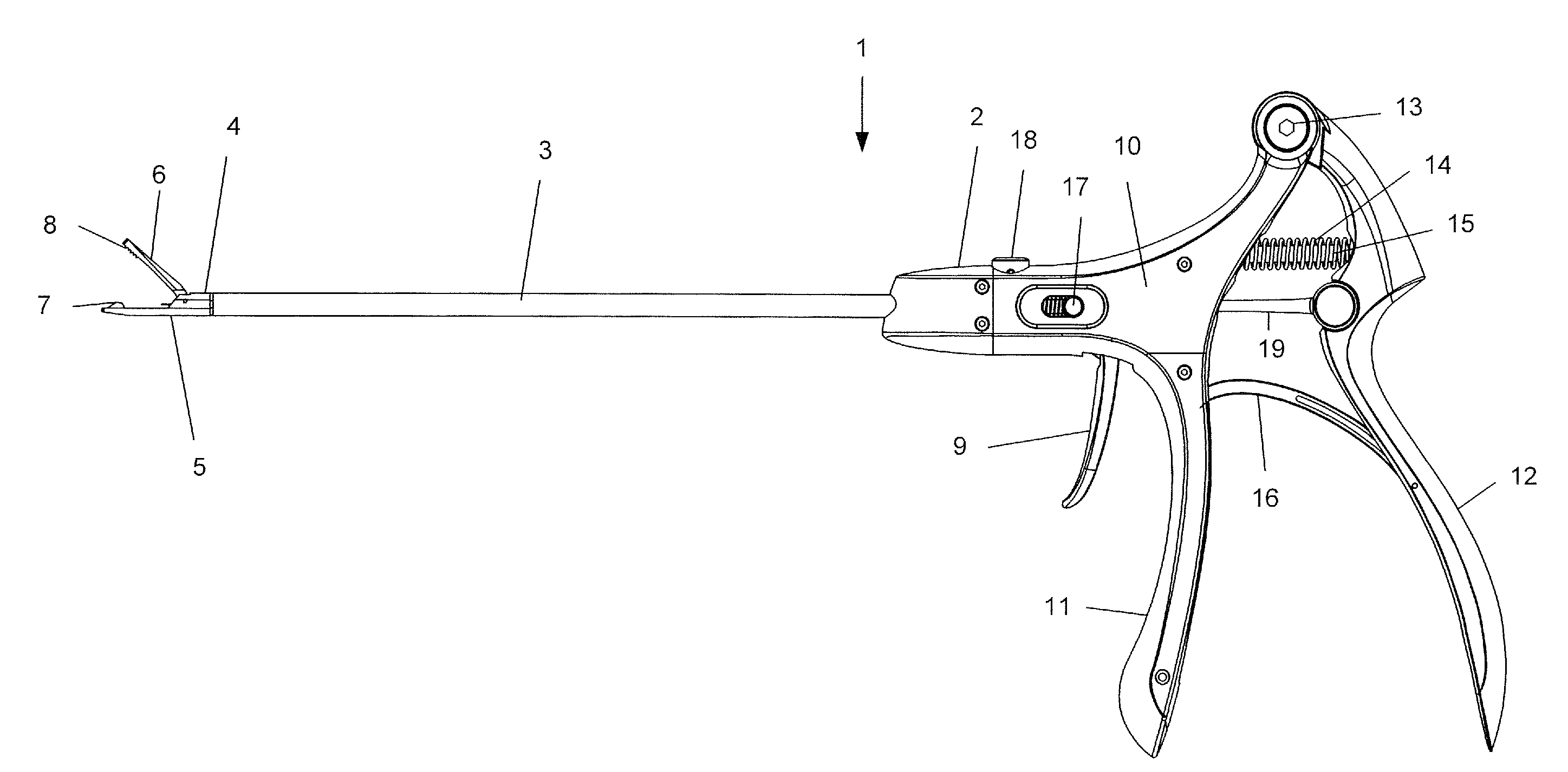
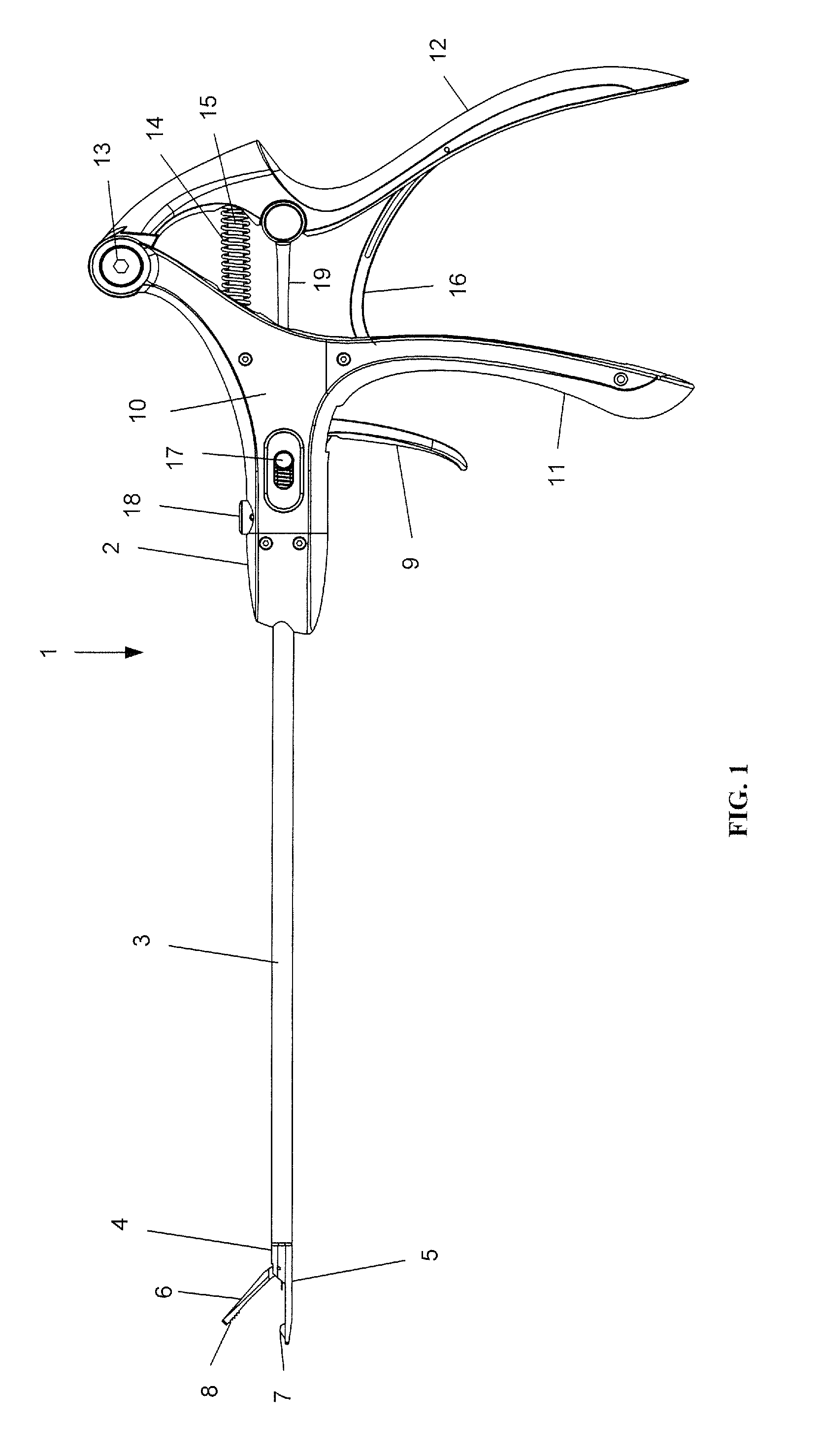
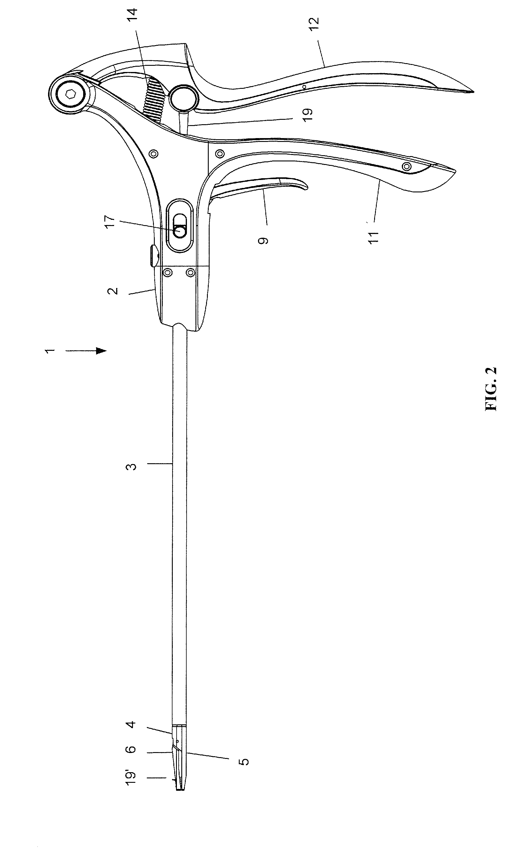
[0031]The present invention is described more fully hereinafter with reference to the accompanying drawings, in which various aspects of a suture passer device and a suture needle are shown. This invention, however, may be embodied in many different forms and should not be construed as limited by the various aspects of the suture passer device and the suture needle presented herein. The detailed description of the suture passer device and the suture needle is provided below so that this disclosure will be thorough and complete, and will fully convey the scope of the present invention to those skilled in the art.

[0032]The detailed description may include specific details for illustrating various aspects of a suture passer device and a suture needle. However, it will be apparent to those skilled in the art that the invention may be practiced without these specific details. In some instances, well known elements may be omitted to avoid obscuring the inventive concepts presented through...


PUM


Abstract

A suture passer device includes a shaft, a handle, an end effector, and a suture capturing member. The shaft has a shaft proximal end and a shaft distal end. The handle assembly is coupled to the shaft proximal end. The end effector is coupled to the shaft distal end. The suture capturing member is within the end effector, is coupled to the handle assembly independently of the shaft, and is configured to capture a suture within the end effector.

Description

BACKGROUND[0001]1. Field[0002]The present disclosure relates to a suture passer device and, more particularly, to a suture passer device configured to capture a suture.[0003]2. Description of Related Art[0004]A suture passer device is a tool for passing a suture through tissue, such as through a rotator cuff. Several existing suture passer devices provide mechanisms for capturing the suture after the suture passes through the tissue. However, the existing suture capture mechanisms may not always effectively capture the suture. As such, there is a need for a suture passing device with an improved mechanism for capturing a suture. Furthermore, there is a need for a corresponding suture needle that works in conjunction with the improved suture passing device.SUMMARY[0005]In an aspect of the disclosure, a suture passer device includes a shaft, a handle, an end effector, and a suture capturing member. The shaft has a shaft proximal end and a shaft distal end. The handle assembly is coupl...

Claims


Application Information

Patent Timeline
Patent Type & Authority Applications(United States)
IPC IPC(8): A61B17/04
CPCA61B17/0469A61B17/0482A61B2017/00367A61B17/0625A61B17/0483
Inventor POWERS, DAVIDSTATES, III, ROBERT G.GILLUM, CHRISTOPH L.PARROTT, DAVID
Owner COST CONTAINMENT
Why Eureka
Try Eureka