
Spray bottle assembly

a technology of spray bottle and assembly, which is applied in the direction of instruments, pliable tubular containers, single-unit apparatuses, etc., can solve the problems of compromising the integrity of the spray device, unable to discharge the various products contained by the current spray device, and limited in the direction and scope of their ability, so as to achieve a wide range of spray angles

Inactive Publication Date: 2011-03-17
MCFARLAND C JUSTIN
View PDF23 Cites 21 Cited by
  • Summary
  • Abstract
  • Description
  • Claims
  • Application Information

AI Technical Summary

Benefits of technology

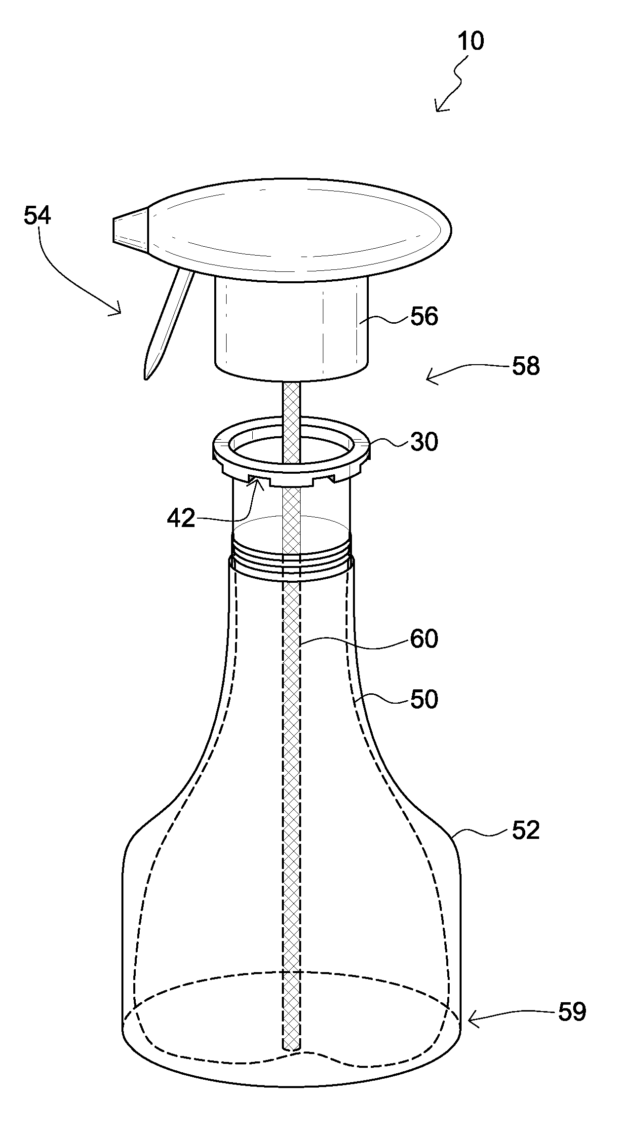
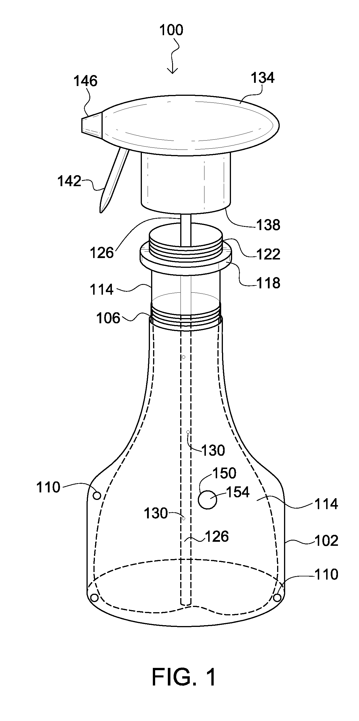
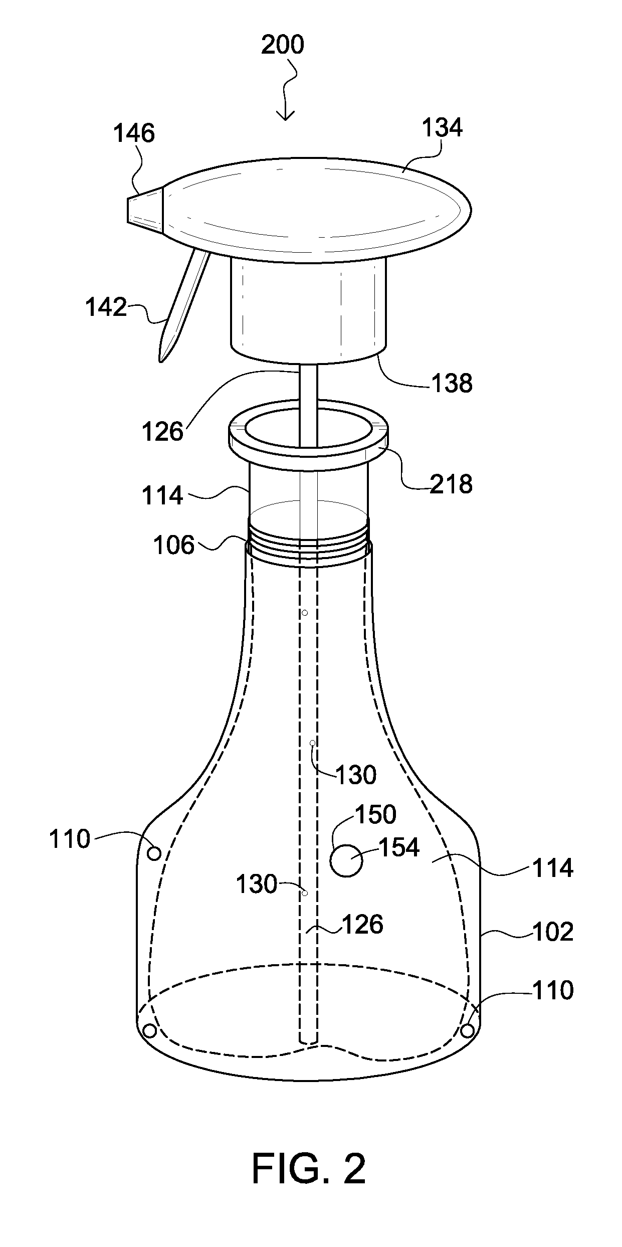
[0008]The present invention has been developed in response to the present state of the art, and in particular, in response to the problems and needs in the art that have not yet been fully solved by currently available spray bottle system. Accordingly, the present invention has been developed to provide a spray bottle system that allows nearly all of a spray bottle contents to be fully discharged during spraying, and which allows operation of the spray bottle over a very wide range of spray angles.
[0011]An advantage of the integrally formed and assembled spray bottle assembly is that it maintains a constant open access of the fluid within the reservoir, to the trigger pump, allowing uninterrupted and complete use of the spray bottle assembly and the product it contains regardless of the direction the bottle is oriented. Another advantage of the integrally formed and assembled spray bottle assembly is that the inner collapsible reservoir is resistant to tampering as being enclosed by the protective outer enclosure and the shroud of the trigger pump, when combined, without substantially restricting fluid communication there through via the vented retaining ring.

Problems solved by technology

Such spray devices have allowed for convenience and portable spraying of many surfaces but have previously been limited in the direction and scope of their ability to spray surfaces from any direction without interruption.
Certain spray devices containing an inner reservoir incorporate holes in the outer bottle exposing the inner reservoir to accidental or intentional tampering thus compromising the integrity of the spray device.
Further, contemporary spray devices have been unable to discharge completely the various products they contain.
The inventions referenced have numerous disadvantages including unreliability, limited spray direction and scope, sporadically interrupted spray flow, exposure to tampering, and inability to use the entire contents of the spray bottle.

Method used


Image

  • Spray bottle assembly
  • Spray bottle assembly
  • Spray bottle assembly

Examples


Embodiment Construction

[0027]For the purposes of promoting an understanding of the principles of the invention, reference will now be made to the exemplary embodiments illustrated in the drawing(s), and specific language will be used to describe the same. It will nevertheless be understood that no limitation of the scope of the invention is thereby intended. Any alterations and further modifications of the inventive features illustrated herein, and any additional applications of the principles of the invention as illustrated herein, which would occur to one skilled in the relevant art and having possession of this disclosure, are to be considered within the scope of the invention.

[0028]Reference throughout this specification to an “embodiment,” an “example” or similar language means that a particular feature, structure, characteristic, or combinations thereof described in connection with the embodiment is included in at least one embodiment of the present invention. Thus, appearances of the phrases an “em...


PUM


Abstract

An integrally formed and assembled spray bottle assembly for maintaining a constant open access of the fluid within the reservoir, to the spray pump, allowing uninterrupted and complete use of the spray bottle assembly and the product it contains. A vented retaining ring adjacent to the opening of an inner collapsible reservoir and protective outer enclosure forms a vented double walled reservoir. The vented retaining ring allows fluid communication between an interior and exterior of the outer enclosure. A trigger pump covers the vented retaining ring while allowing fluid communication there through. A conduit is disposed within the inner collapsible reservoir.

Description

CROSS-REFERENCE TO RELATED APPLICATIONS[0001]This application is a Continuation-in-Part Application of, under 35 U.S.C. §121, and claims priority to, under 35 U.S.C. §121, U.S. Non-Provisional application Ser. No. 11 / 278,776, entitled Spray Bottle System, by C. Justin McFarland, filed on Apr. 5, 2006.BACKGROUND OF THE INVENTION[0002]1. Field of the Invention[0003]The present invention relates to spray bottle assemblies, more specifically a spray bottle assembly that maintains a constant access of fluid to the spray pump.[0004]2. Description of the Related Art[0005]In the related art, it has been known to use devices for spraying various liquids. Spray devices have been developed for applying cleaning products, pesticides, and aromatics to name a few. Such spray devices have allowed for convenience and portable spraying of many surfaces but have previously been limited in the direction and scope of their ability to spray surfaces from any direction without interruption. Certain spray...

Claims


Application Information

Patent Timeline
IPC IPC(8): B65D35/56
CPCB05B11/0016B05B11/0043B05B15/005B05B11/3057B05B11/0056B05B15/30B05B11/0044B05B11/026B05B11/1057
Inventor MCFARLAND, C. JUSTIN
Owner MCFARLAND C JUSTIN
Learn More