Post pulling device

a technology of pulling device and post, which is applied in the direction of cell components, cell component details, manufacturing tools, etc., can solve the problems of difficult extraction or removal of fencing posts

Inactive Publication Date: 2011-03-17
RING GJERDE TAMMY
View PDF18 Cites 5 Cited by
  • Summary
  • Abstract
  • Description
  • Claims
  • Application Information

AI Technical Summary

Problems solved by technology

Consequently, the extracting or removal of th

Method used


Image

  • Post pulling device
  • Post pulling device
  • Post pulling device

Examples


Embodiment Construction

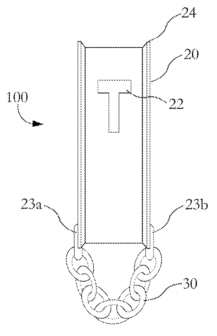
[0011]The present invention provides a post-pulling device to assist in the extraction and removal of T-shaped fencing posts. The post-pulling device according to the present invention provides a device designed for the pulling or extracting of the fence posts used widely on ranches and farms. FIG. 1 depicts a Post-Pulling Device 100 according to the present invention. The Post-Pulling Device 100 of the present invention includes an I-Beam Body 20 and a Pull Chain 30. The Pull Chain 30 is connected to the I-Beam Body 20 a first end thereof and provides a means to pull or remove the T-posts once inserted into the Post-Pulling Device 100.

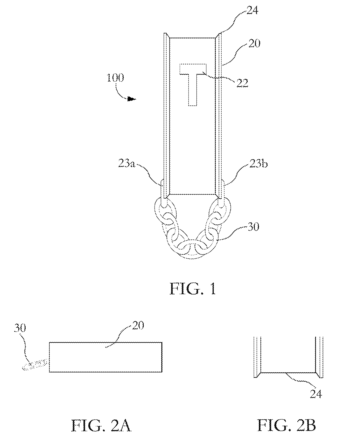
[0012]The Pull Chain 30 is attached to the I-Beam Body 20 by Two Welded Connections 23a, 23b. Near a second end of the I-Beam Body 20, a Post Insertion Opening 22 is provided. The Post Insertion Opening 22 is a T-shaped opening for the insertion of a T-shaped post. Beyond the T-Shaped Opening 22 is the second end of the I-Beam Body 20.

[0013]FIG. 2A sh...


PUM


Abstract

The present invention relates to a post-pulling device for the extraction of T-shaped posts and a method of using the same. The post-pulling device according to the present invention includes: an I-beam body; a pull chain, where said pull chain is permanently attached to a first end of the I-beam body; and a post insertion opening near a second end of the I-beam body, where said opening allows for the insertion of a T-shaped posted. The pull chain may be welded to the I-beam body. In one particular embodiment, the I-beam body may include two beveled sidewalls and the opening may be a T-shaped opening.

Description

BACKGROUND OF THE INVENTION[0001]1. Field of Invention[0002]The present invention relates to a device to assist in the pulling of metal fencing posts.[0003]2. Description of Related Art[0004]Agricultural fencing may be used to enclose or limit the movement of livestock on a ranch or farm. Fencing used for this particular purpose may be made from various materials depending on the terrain, location and types of animals being confined. The fences utilized on farms and ranches help to restrict the movement of livestock and prevent livestock from wandering onto state or federal highways and consequently causing a collision. The types of fences utilized may include wire, barbwire, wooden, woven wire and even electrical charged fencing. The typical fence used on a farm or ranch may be up to about 4 feet in height where a series of posts are used to mount or construct the fence. Posts used for the fence may include wooden posts and steel T-shaped posts. Posts may be placed about 10 to 20 f...

Claims


Application Information

Patent Timeline
IPC IPC(8): E04H17/26
CPCY10T29/49822E04H17/265
Inventor RING-GJERDE, TAMMY
Owner RING GJERDE TAMMY
Why Eureka
Try Eureka