Methods for digital image compression

a digital image and compression technology, applied in the field of computer software, can solve the problems of large bandwidth for digital image transmission across networks, significant amount of time may be required for transmitting digital images, and large amount of computer hardware to store digital images

Active Publication Date: 2011-03-31
DEAVER FREDERIC SCOTT +1
View PDF7 Cites 8 Cited by
  • Summary
  • Abstract
  • Description
  • Claims
  • Application Information

AI Technical Summary

Problems solved by technology

In various aspects, significant amounts of computer hardware may be required to store the digital images.
The transmission of digital images across networks may require large bandwidth because of the large size digital images may have.
Also, because of the large size digital images may have, significant amounts of time may be required to transmit the digital images.
While methods exist for compressing digital images, may existing methods lose information during the compression.

Method used


Image

  • Methods for digital image compression
  • Methods for digital image compression
  • Methods for digital image compression

Examples


example i

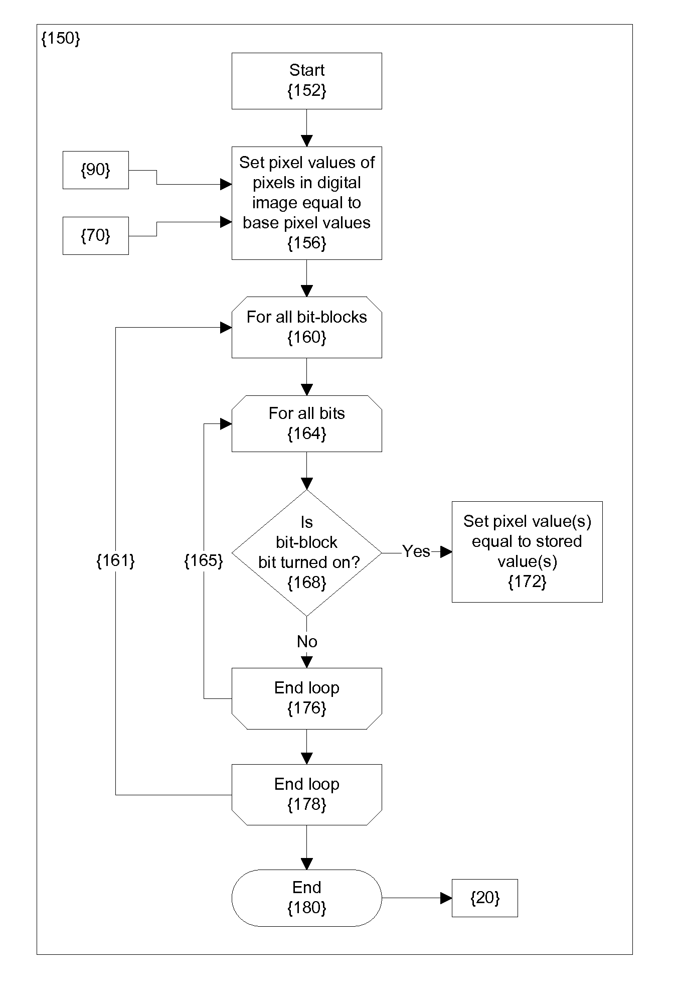
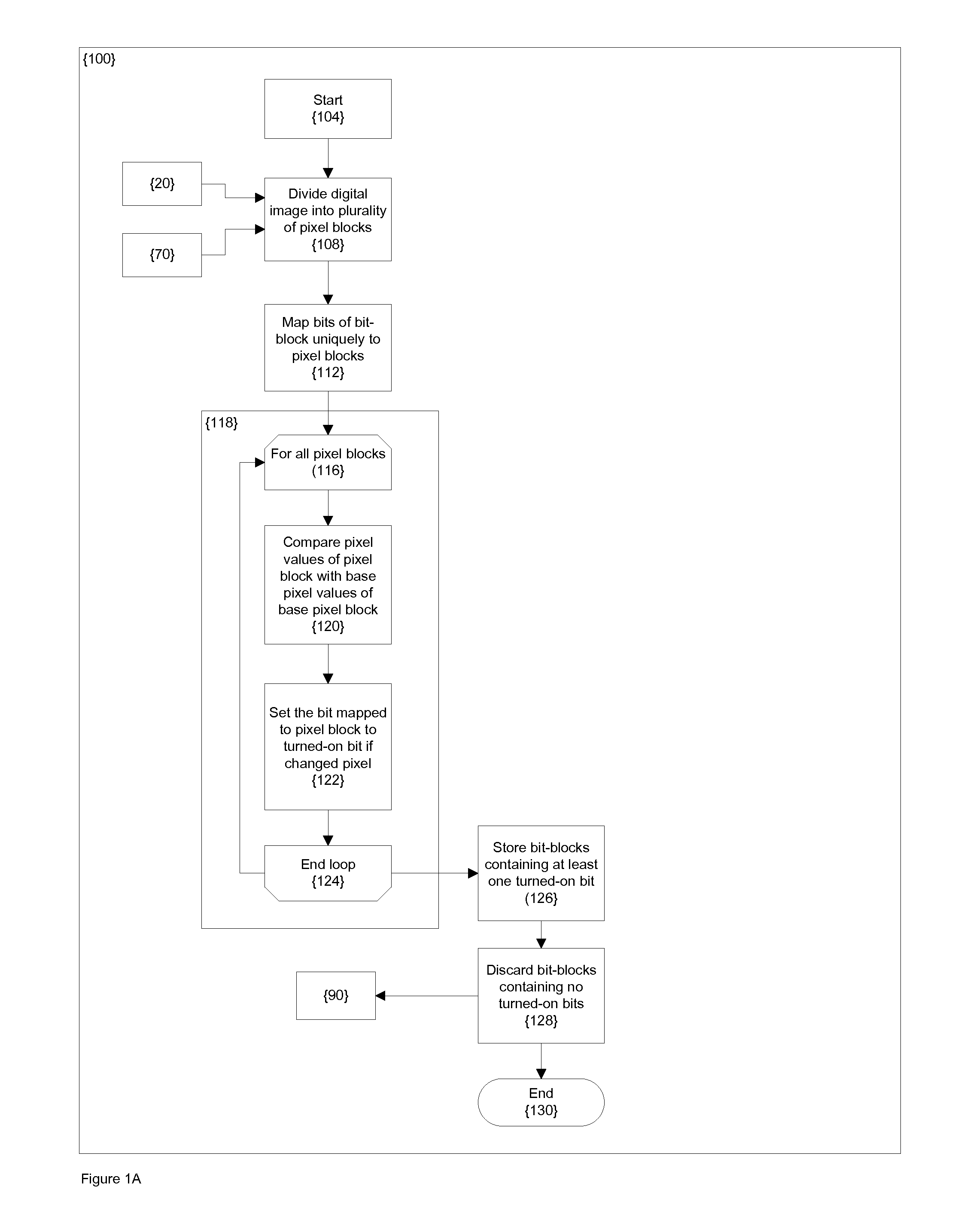
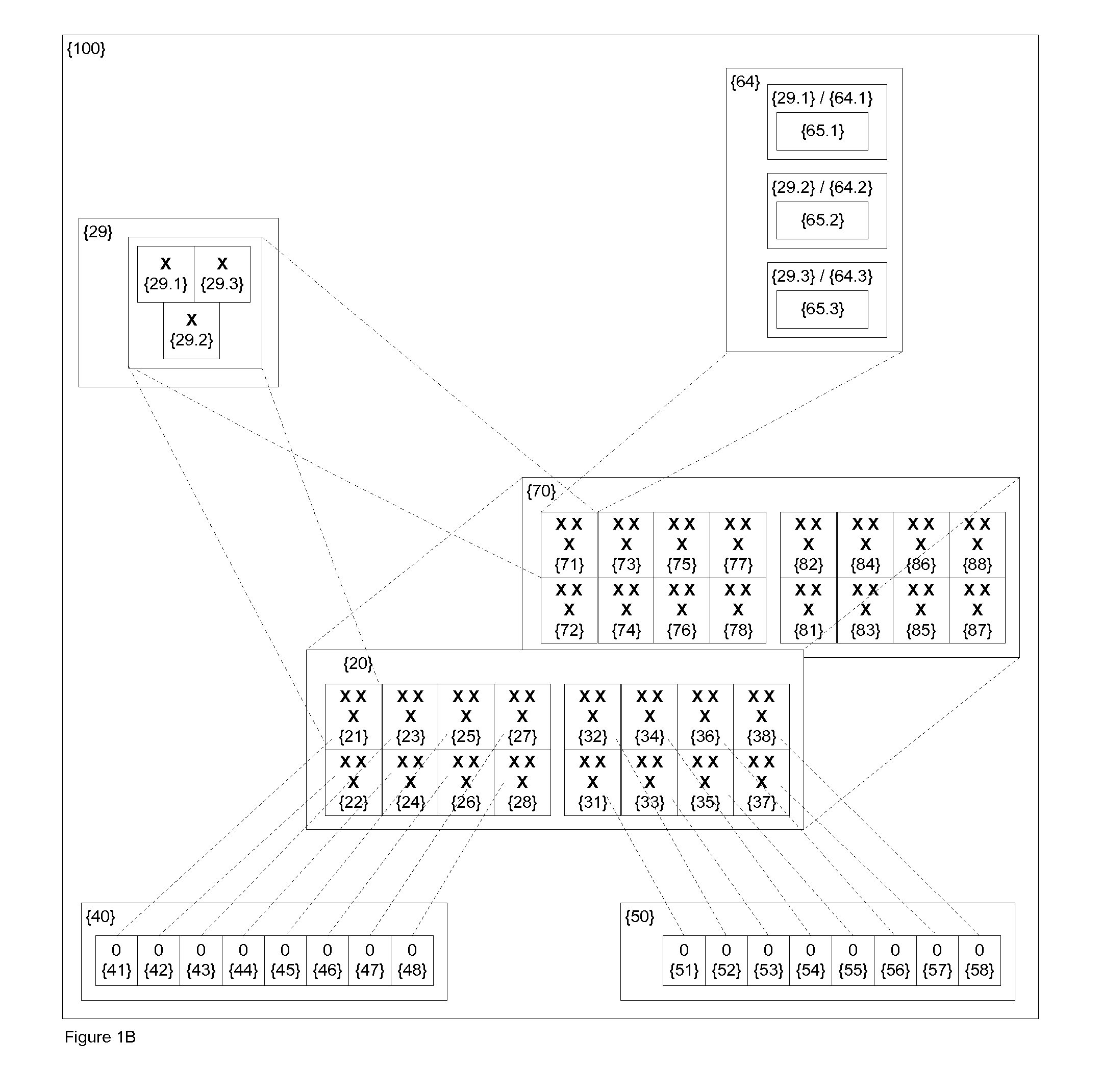
[0038]FIGS. 1A to 1D illustrates method 100 that compresses digital image 20 into compressed image 90. As illustrated in FIG. 1A, method 100 is entered at step 104. At step 108, the digital image 20 is divided into pixel-blocks 21-28, 31-38, as illustrated in FIG. 1B. Each pixel bock, such as pixel-blocks 21-28, 31-38, contains one or more pixels 29. For example, in this implementation, pixel-block 21 contains pixels 29.1, 29.2, 29.3.

[0039]Method 100 proceeds from step 108 to step 112, and, at step 112, the bits 41-48, 51-58 within bit-blocks 40, 50 are mapped uniquely to the pixel-blocks 21-28, 31-38. In this implementation, bit-blocks 40, 50 are represented as 8-bit bytes. At step 108, each of bits 41-48 in bit-block 40 and each of bits 51-58 in bit-block 50 are mapped uniquely to a corresponding pixel-block of pixel-blocks 21-28, 31-38, so that there is a one-to-one correspondence between each of bits 41-48, 51-58 and pixel-blocks 21-28, 31-38. For example, bit 41 is mapped uniqu...

example ii

[0050]In Example II, method 300, which compresses larger image 305 into compressed image 397, is generally illustrated by flow chart in FIGS. 3A and 3B. A larger image 305 and a base image 303 are inputs into method 300, as illustrated. Method 300 begins at step 302 and proceeds from step 302 to step 306. At step 306, the larger image 305 is compared with the base image 303 to find changed pixels 339, where changed pixels 339 have a pixel value in the larger image 305 that differs from the base pixel value in the base image 303.

[0051]At step 310, digital image 315 is defined from the larger image 305 such that the digital image 315 forms the smallest rectangle that encloses all of the changed pixels 339 in the larger image 305. There are no changed pixels 339 in the larger image 305 that fall outside the boundaries of the digital image 315. In some implementations, the digital image 315 may include the entirety of the larger image 305, while, in other implementations, the digital im...


PUM


Abstract

Methods, systems, and compositions of matter are disclosed herein for the compression of digital image(s) and for the expansion of digital images so compressed. In various aspects, the digital images may be compressed and the compressed images expanded substantially without loss of information.

Description

BACKGROUND OF THE INVENTION[0001]1. Field[0002]The present disclosure relates to computer software, and, more particularly for computer software for image compression.[0003]2. Description of the Related Art[0004]A wide variety of endeavors may produce large numbers of digital images. In various aspects, significant amounts of computer hardware may be required to store the digital images. The transmission of digital images across networks may require large bandwidth because of the large size digital images may have. Also, because of the large size digital images may have, significant amounts of time may be required to transmit the digital images.[0005]In order to address these problems, digital images may be compressed in order to reduce the size of the digital image that is stored or transmitted. While methods exist for compressing digital images, may existing methods lose information during the compression.[0006]Accordingly, for at least the above reasons, there is a need for metho...

Claims


Application Information

Patent Timeline
Patent Type & Authority Applications(United States)
IPC IPC(8): G06K9/36
CPCH04N19/507
Inventor DEAVER, F. SCOTT
Owner DEAVER FREDERIC SCOTT
Why Eureka
Try Eureka