Waste heat recovery system

Inactive Publication Date: 2011-04-21
TOYOTA IND CORP
View PDF3 Cites 32 Cited by
  • Summary
  • Abstract
  • Description
  • Claims
  • Application Information

AI Technical Summary

Benefits of technology

[0006]In accordance with an aspect of the present invention, the waste heat recovery system of an engine includes a Rankine cycle, a first bypass passage, a first valve and a control unit. The Rankine cycle allows a working fluid to circulate therethrough. The Rankine cycle has a first heat exchanger, a second heat exchanger, an expander and a condenser. The first heat exchanger is provided for exchanging heat between the working fluid and the engine or a first intermediate medium exchanging heat with the engine. The second heat exchanger is provided for exchanging heat between the working fluid and an exhaust gas of the engine or a second intermediate medium exchanging heat with the exhaust gas of the engine. The expander is provided for expanding the

Problems solved by technology

When the temperature of the cooling water of the engine is low as in the case of a start-up of the engine, the fuel efficiency of the engine generally deteriorates.
However, the working fluid

Method used


Image

  • Waste heat recovery system
  • Waste heat recovery system
  • Waste heat recovery system

Examples


first embodiment

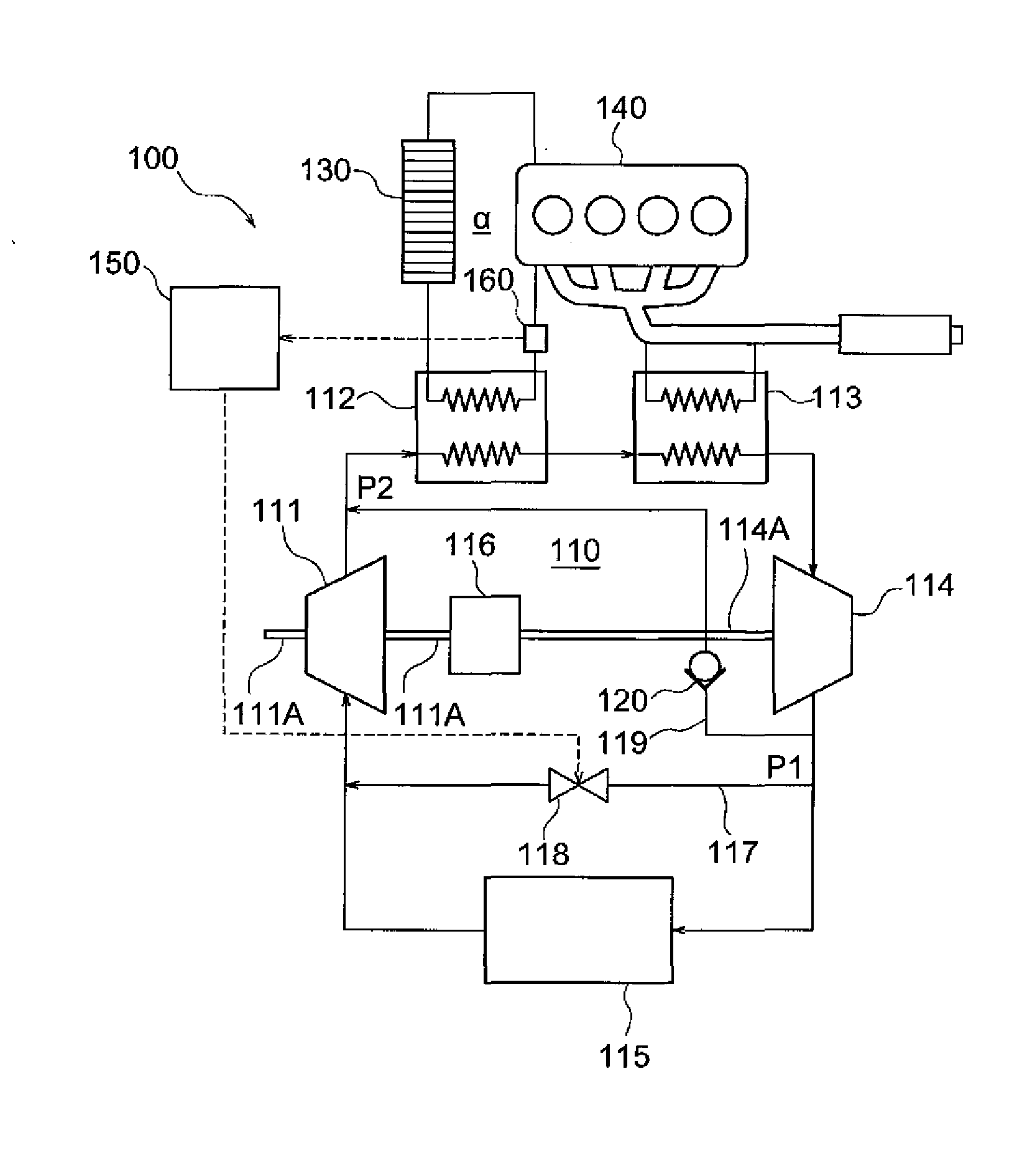
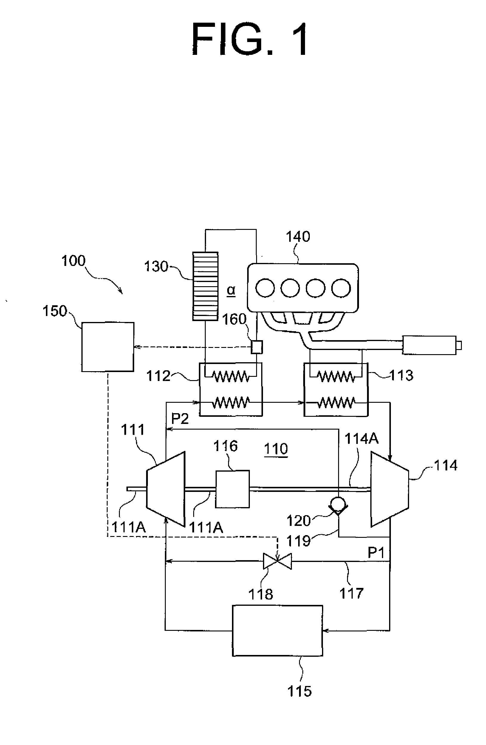
[0017]The following will describe the embodiments of the present invention with reference to the accompanying drawings. FIG. 1 shows a waste heat recovery system 100 according to the present invention. The waste heat recovery system 100 includes a Rankine cycle 110. The Rankine cycle 110 has a gear pump 111, a cooling water boiler 112, an exhaust gas boiler 113, an expander 114 and a condenser 115. The gear pump 111 is provided for pumping a working fluid. The cooling water boiler 112 is provided for exchanging heat between the working fluid and a cooling water exchanging heat with an engine 140, serving as the first heat exchanger of the present invention. The exhaust gas boiler 113 is provided for exchanging heat between the working fluid and an exhaust gas of the engine 140, serving as the second heat exchanger of the present invention. The expander 114 is provided for expanding the working fluid heated and vaporized by the cooling water boiler 112 and the exhaust gas boiler 113 ...

second embodiment

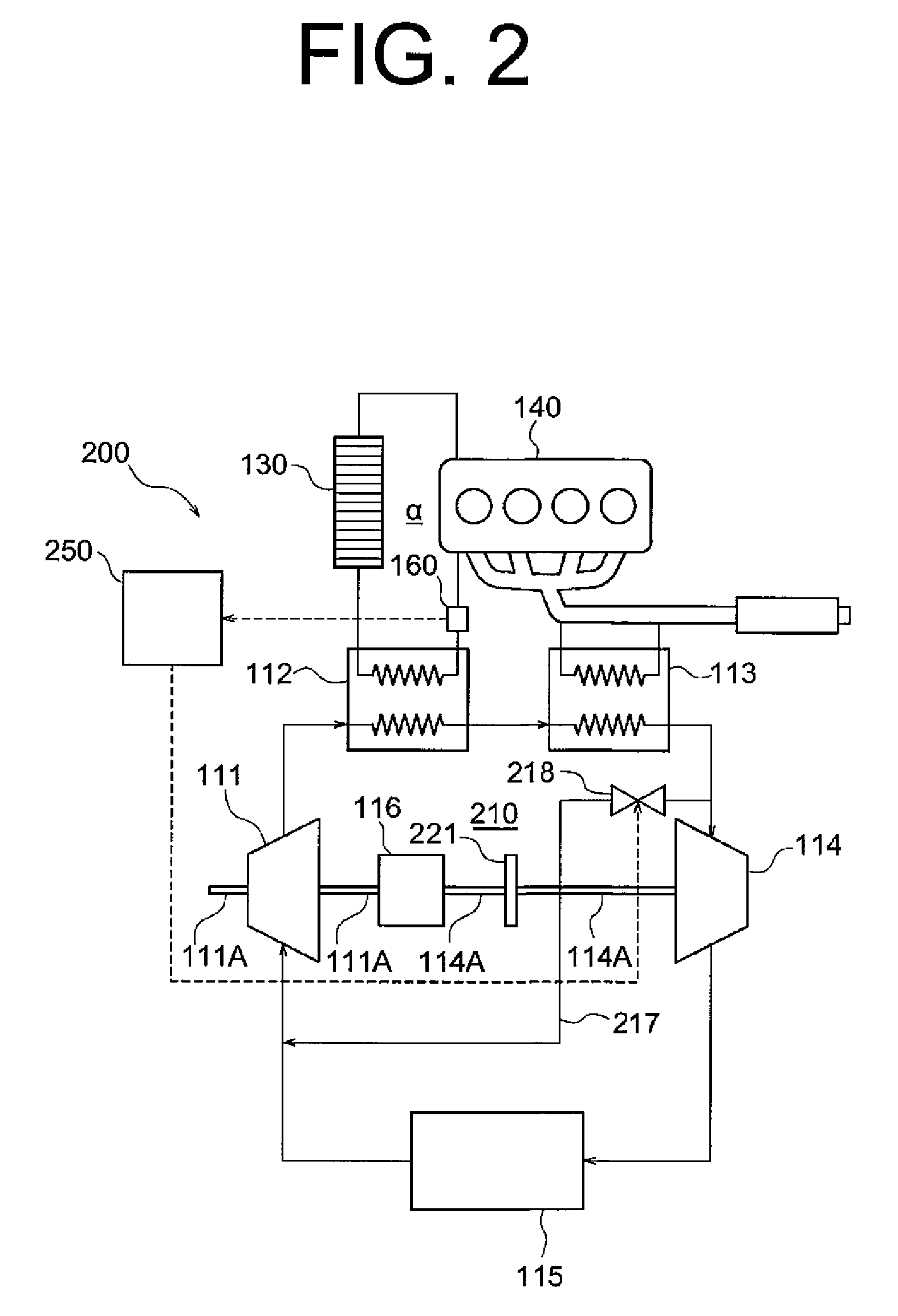
[0031]The following will describe the operation of the waste heat recovery system 200 of the The description will be made for two cases, i.e. one case where the temperature of the cooling water of the engine 140 is the first predetermined value Th1 or higher and the other case where the temperature of the cooling water of the engine 140 is lower than the first predetermined value Th1.

[0032]When the temperature of the cooling water of the engine 140 obtained by the temperature sensor 160 is the first predetermined value Th1 or higher, the control unit 250 causes the electromagnetic valve 218 to close thereby to close the first bypass passage 217.

[0033]With the first bypass passage 217 closed, the working fluid delivered from the gear pump 111 circulates through the cooling water boiler 112, the exhaust gas boiler 113, the expander 114 and the condenser 115 in this order in the Rankine cycle 210. The output shaft 114A of the expander 114 is driven to rotate by the expansion of the wo...

third embodiment

[0043]The following will describe the operation of the waste heat recovery system 300 of the The description will be made for two cases, i.e. one case where the temperature of the cooling water of the engine 140 is a second predetermined value Th2 that is slightly higher, e.g. by two degrees, than the aforementioned first predetermined value Th1 or higher and the other case where the temperature of the cooling water of the engine 140 is lower than the first predetermined value Th1.

[0044]When the temperature of the cooling water of the engine 140 is the second predetermined value Th2 or higher, the control unit 350 moves the first three-way valve 318 to such a position that allows the working fluid flowed out of the expander 114 into the condenser 115. That is, the first bypass passage 317 is closed thereby to cut off the circulation of the working fluid through the first bypass passage 317. In addition, the control unit 350 moves the second three-way valve 323 to such a position th...


PUM


Abstract

The waste heat recovery system of an engine includes a Rankine cycle, a first bypass passage, a first valve and a control unit. The Rankine cycle allows a working fluid to circulate therethrough. The Rankine cycle has a first heat exchanger, a second heat exchanger, an expander and a condenser. The first heat exchanger exchange heat between the working fluid and the engine or a first intermediate medium exchanging heat with the engine. The first bypass passage allows the working fluid to pass therethrough. One end of the first bypass passage is located at an upstream side of the condenser and the other end is located at a downstream side of the condenser. The first valve opens and closes the first bypass passage. When temperature of the engine or the first intermediate medium is lower than a first predetermined value, the control unit opens the first valve.

Description

BACKGROUND OF THE INVENTION[0001]The present invention relates to a waste heat recovery system and more particularly to a waste heat recovery system using a Rankine cycle.[0002]The waste heat recovery system using a Rankine cycle has been developed to recover mechanical energy (power) from waste heat of a vehicle engine. The Rankine cycle generally includes a pump that pumps working fluid, a heat exchanger that heats working fluid by the waste heat of an engine, an expander that expands the heated working fluid to recover mechanical energy, and a condenser that condenses the expanded working fluid.[0003]Japanese Patent Application Publication No. 2007-85195 discloses a waste heat recovery system having two heat exchangers. The Rankine cycle of this waste heat recovery system includes a first heat exchanger that heats working fluid by heat exchange with a cooling water of the engine, and a second heat exchanger that heats the working fluid by heat exchange with exhaust gas of the eng...

Claims


Application Information

Patent Timeline
IPC IPC(8): F01K9/00
CPCF01K27/02F01K23/065
Inventor MORI, HIDEFUMIIGUCHI, MASAOENOKIJIMA, FUMINOBUKAWAGUCHI, MASAHIRO
Owner TOYOTA IND CORP
Why Eureka
Try Eureka