Devices for storing energy in the mechanical deformation of nanotube molecules and recovering the energy from mechanically deformed nanotube molecules

a technology of mechanical deformation and nanotube molecules, which is applied in the field of energy storage, can solve the problems of relatively low energy storage density of nanotube molecules, and it is quite difficult to demonstrate these properties experimentally, and achieve the effect of mechanical energy recovery

Inactive Publication Date: 2008-12-11
MASSACHUSETTS INST OF TECH
View PDF7 Cites 21 Cited by
  • Summary
  • Abstract
  • Description
  • Claims
  • Application Information

AI Technical Summary

Benefits of technology

[0008]According to another aspect of the invention, there is provided method of producing mechanical energy in or transferring mechanical energy to an energy storage device. The method includes providing at least one nanotube and allowing the elasticity of the at least one nanotube to convert the mechanical energy into the appropriate levels of strain on the at least one nanotube to produce stored energy. Also, the method includes allowing the elasticity of the at least one nanotube to relax the appropriate levels of strain and recover the mechanical energy for use external to the energy storage device.

Problems solved by technology

Their disadvantage lies in their relatively low energy storage density, which is about 600 Joule per liter for steel springs.
It has however been quite difficult to demonstrate these properties experimentally, although suggestive studies have been performed on the compression of highly disordered macroscopic assemblies of carbon nanotubes (“Mechanical Energy Storage in Carbon Nanotube Springs,” S. A. Chesnokov, V. A. Nalimova, A. G. Rinzler, R. E. Smalley and J. E. Fischer, Physical Review Letters 82, 343-346, 1999) as well as on the imprecisely controlled tension of single nanotubes (“Strength and Breaking Mechanism of Multiwalled Carbon Nanotubes under Tensile Load,” Min-Feng Yu, O. Lourie, M. J. Dyer, K. Moloni, T. F. Kelly and R. S. Ruoff, Science Magazine 287, 637-640, 2000).

Method used


Image

  • Devices for storing energy in the mechanical deformation of nanotube molecules and recovering the energy from mechanically deformed nanotube molecules
  • Devices for storing energy in the mechanical deformation of nanotube molecules and recovering the energy from mechanically deformed nanotube molecules
  • Devices for storing energy in the mechanical deformation of nanotube molecules and recovering the energy from mechanically deformed nanotube molecules

Examples


Embodiment Construction

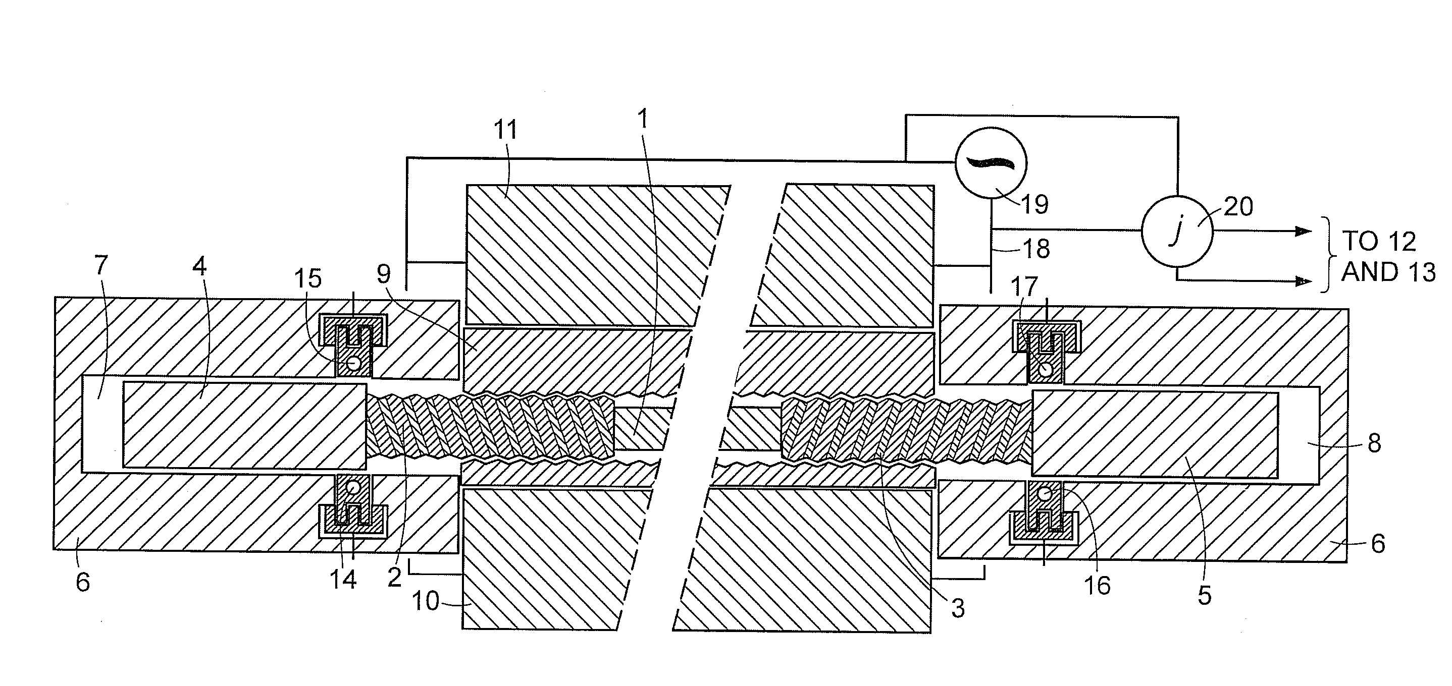
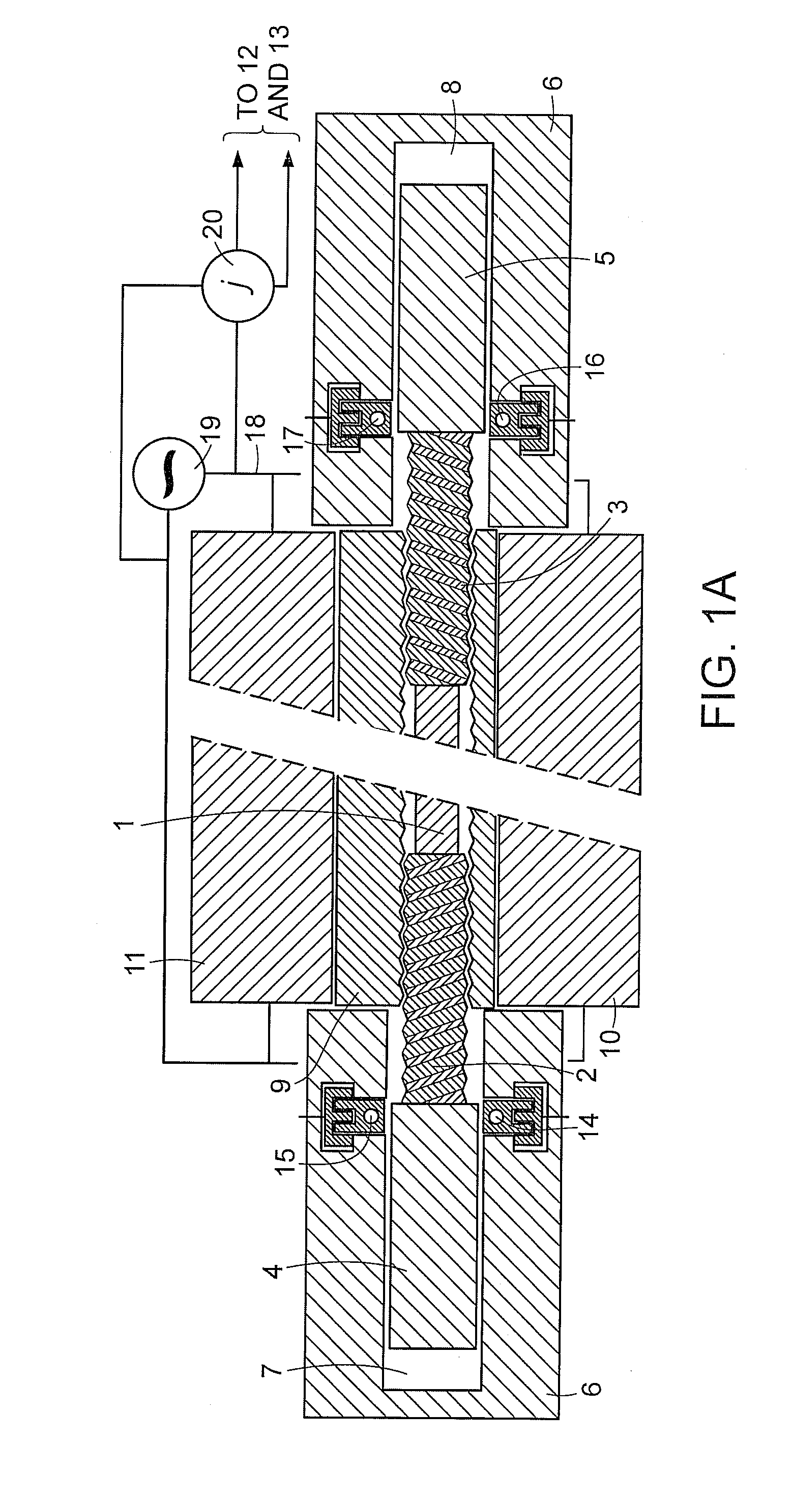
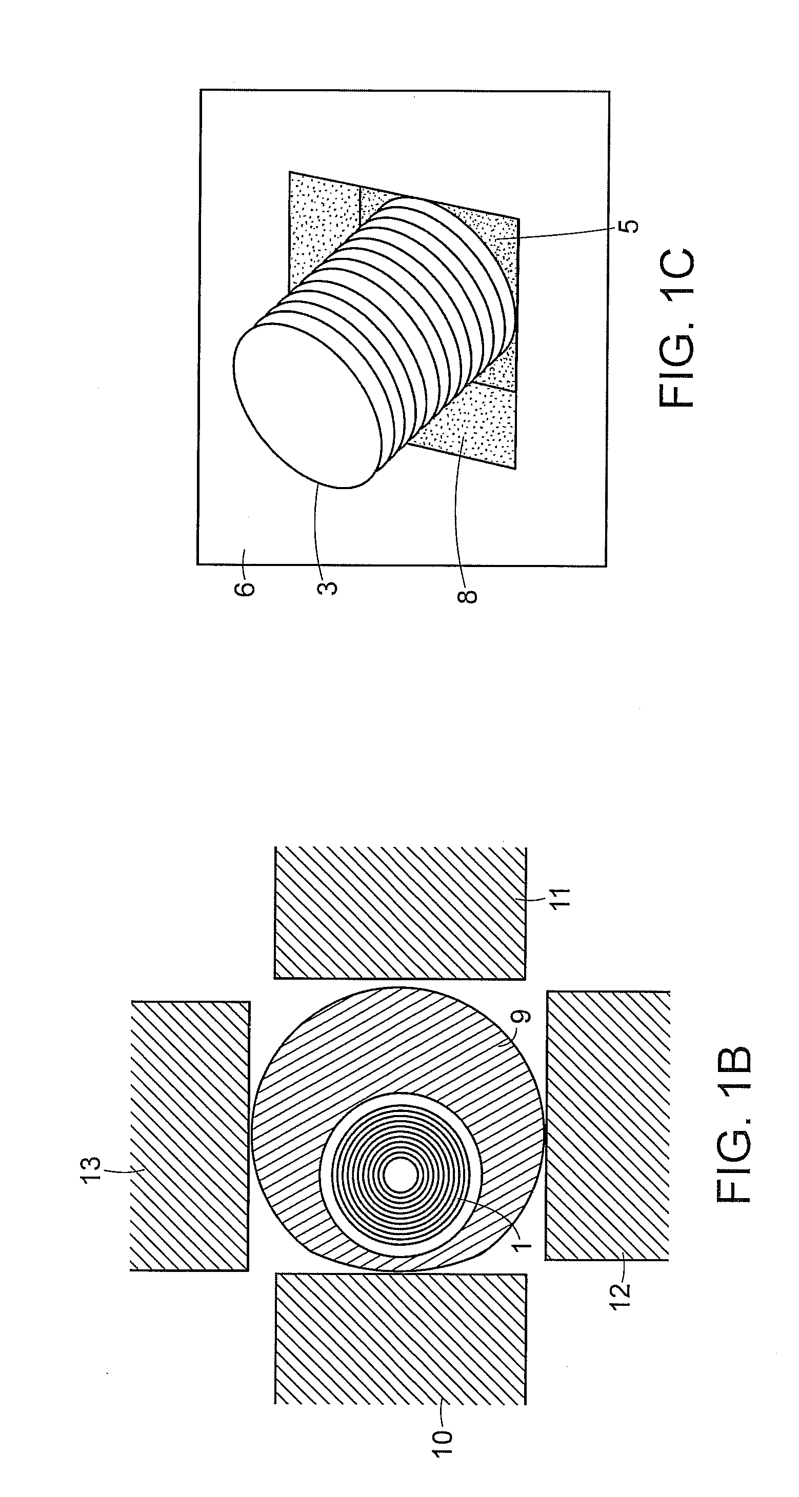
[0012]The invention provides a technique to utilize nanotubes as “super-springs” in which one can store and from which one can recover energy for subsequent use, either directly in the form of mechanical energy or in the form of electricity generated from this mechanical energy. The technical rational for this new use of nanotubes is as follows.

[0013]Nanotube molecules are not only several times stiffer than steel, but they are also far more flexible than steel. In addition, nanotubes are not prone to fatigue from repeated use, as metal springs are. Since the energy stored in any spring is approximately proportional to the stiffness and to the square of the displacement, these two facts together imply that it should be possible to store much more energy in a spring composed entirely or largely of nanotube molecules than it would be in any other known kind of spring of comparable size and weight.

[0014]An estimate of the maximum energy density of a nanotube spring is readily obtained ...


PUM

PropertyMeasurementUnit
energy storage densityaaaaaaaaaa
stored energyaaaaaaaaaa
piezoelectricaaaaaaaaaa

Abstract

An energy storage device includes at least one nanotube. An energy storage mechanism converts energy external to the device into the appropriate levels of strain on the at least one nanotube to produce stored energy, and an energy recovery mechanism converts the energy released by relaxing the at least one nanotube back to energy external to the device.

Description

PRIORITY INFORMATION[0001]This application claims priority from provisional application Ser. No. 60 / 836,427 filed Aug. 8, 2006, which is incorporated herein by reference in its entirety.BACKGROUND OF THE INVENTION[0002]The invention relates to the field of energy storage, in particular to storing energy in the precisely controlled mechanical deformation of single or highly ordered assemblies of nanotube molecules, and to recovering it at a later time in order to perform useful work, for example to power an electronic device or a motor vehicle.[0003]The deformation of elastic springs, made for example out of rubber or steel, is one of the oldest and best-known forms of energy storage. It has been widely used to power clocks and wrist watches as well as, albeit much less widely, a means of powering electronic devices such as radios (Trevor Baylis, UK patent #2,262,324 A) or vehicles such as bicycles (Jason Dunkley, U.S. Pat. No. 6,557,877 B2). The advantages of mechanical springs over...

Claims


Application Information

Patent Timeline
Patent Type & Authority Applications(United States)
IPC IPC(8): H01M10/00H01M10/04
CPCB81B3/0027B82Y15/00B82Y30/00F03G1/02Y10T29/49108H02N1/00H02N11/002Y10S977/725H02K7/18Y02P70/50
Inventor HAVEL, TIMOTHY F.LIVERMORE-CLIFFORD, CAROL
Owner MASSACHUSETTS INST OF TECH
Why Eureka
Try Eureka