Expander and heat pump using the expander

Inactive Publication Date: 2009-10-01
PANASONIC CORP
View PDF4 Cites 13 Cited by
  • Summary
  • Abstract
  • Description
  • Claims
  • Application Information

AI Technical Summary

Benefits of technology

[0025]According to the expander of the present invention, it is possible to adjust the timing for shifting from the suction process for the working fluid to the expansion process for the working fluid by opening/closing the differential pressure valve of the second suction port. Specifically, it is possible to control the ratio of the time length for which the expansion process is performed to the time length for which the suction process is performed. As a result, according to the present invention, it becomes possible to change the foregoing ratio (Ves/Vcs), and it is possible to avoid the constraint of constant density ratio in, for example, a refrigeration

Problems solved by technology

Thus, the refrigeration cycle is hindered from being controlled freely.
Therefore, the refrigeration cycle cannot be operated efficiently if the temperature and the pressure cannot be controlled freely.
In this configuration, however, the energy of expansion of the working fluid that passes through the sub-circuit cannot be recovered.
The problem of the inefficiency in recovering the energy of expansion of the working fluid is noticeable in the case of using an expander-compressor unit, bu

Method used


Image

  • Expander and heat pump using the expander
  • Expander and heat pump using the expander
  • Expander and heat pump using the expander

Examples


Example

FIRST EMBODIMENT

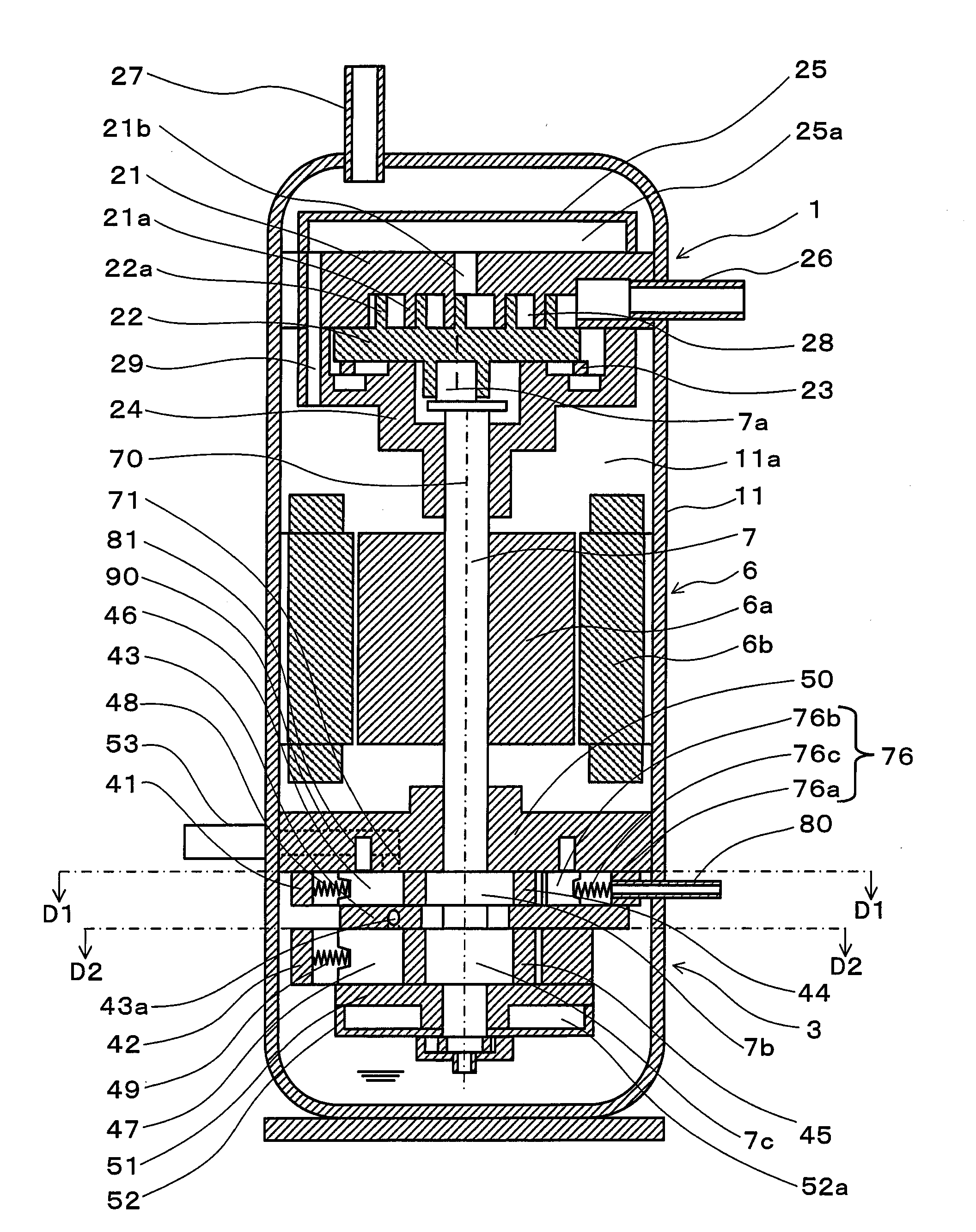
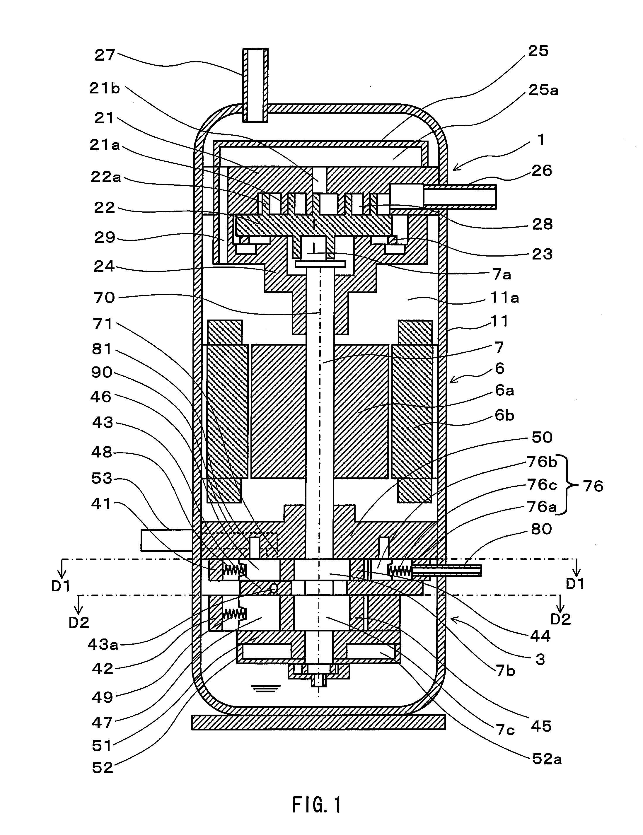
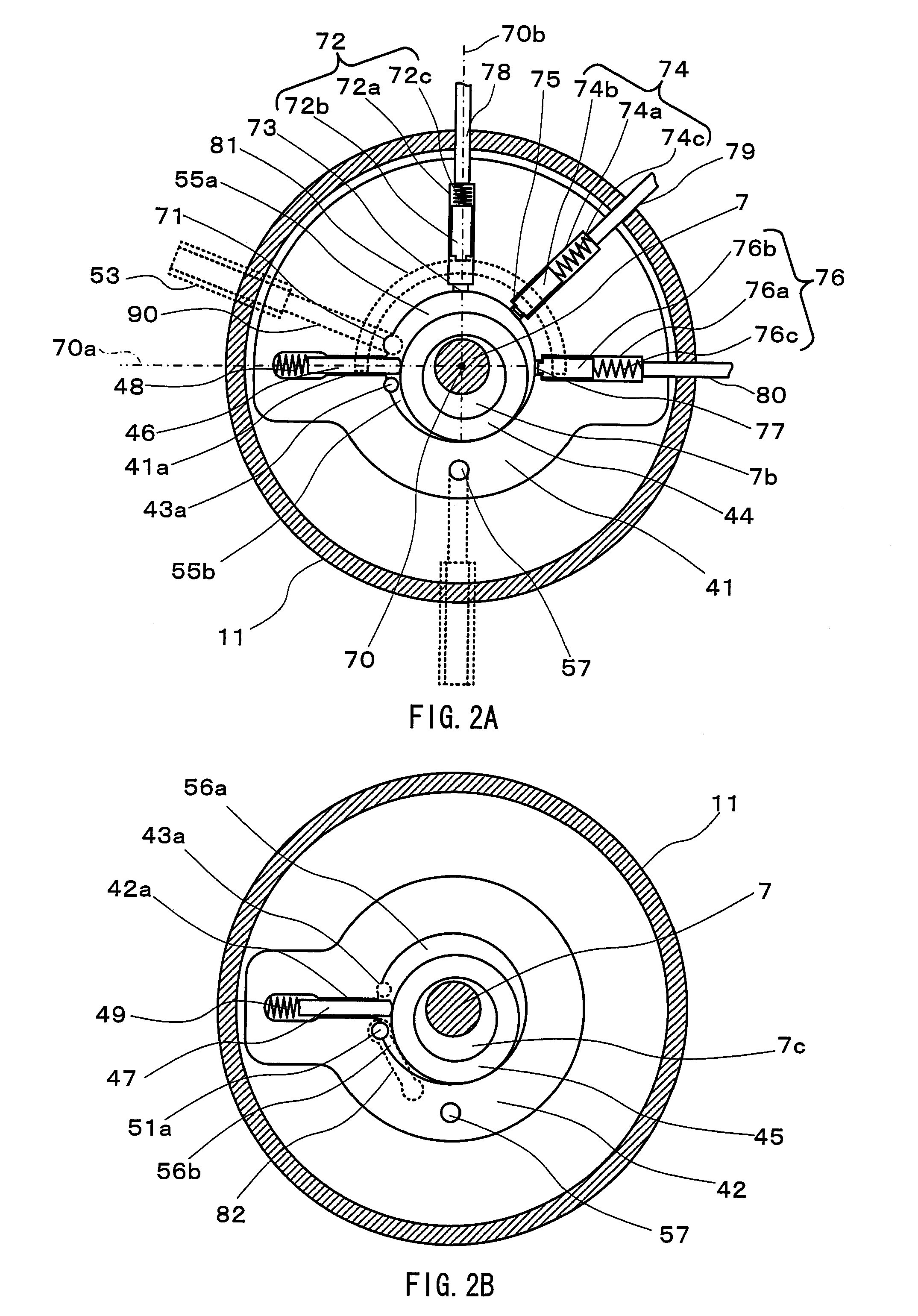
[0044]FIG. 1 is a vertical cross-sectional view illustrating an expander-compressor unit according to a first embodiment of the present invention. FIG. 2A is a horizontal cross-sectional view of an expander section of the expander-compressor unit shown in FIG. 1, taken along line D1-D1 of FIG. 1. FIG. 2B is a horizontal cross-sectional view of the expander section of the expander-compressor unit, taken along line D2-D2.

[0045]An expander-compressor unit according to the present embodiment includes a closed casing 11, a scroll type compressor section 1 disposed in an upper portion of the closed casing, a two-stage rotary expander section 3 disposed in a lower portion of the closed casing, a rotation motor 6 disposed between the compressor section 1 and the expander section 3 and having a rotor 6a and a stator 6b, and a shaft 7 for coupling the compressor section 1, the expander section 3, and the rotation motor 6 to one another.

[0046]The scroll type compressor section ...

Example

SECOND EMBODIMENT

[0101]The first embodiment has described a two-stage rotary expander (expander section 3) that, in addition to the first expansion mechanism, further includes a second expansion mechanism having a working chamber in communication with a working chamber in the first expansion mechanism through a communication port.

[0102]The expander section 3 may be used alone. In other words, it may be used as an expander separate from a compressor. FIG. 9 illustrates the configuration of a power recovery type refrigeration cycle apparatus employing the separate-type expander. This apparatus has a similar configuration to the refrigeration cycle apparatus shown in FIG. 3 (the same members are denoted by the same reference numerals, and the descriptions thereof are omitted). In place of the expander-compressor unit (reference numerals 1, 3, 6, and 7 in FIG. 3), this apparatus includes a compressor 61 and an expander 63, separated from each other, a rotation motor 66 connected to the ...

Example

THIRD EMBODIMENT

[0104]The present embodiment provides a refrigeration cycle apparatus that has the configuration shown in FIG. 11, in place of the configuration shown in FIG. 3. This apparatus has a similar configuration to that of the refrigeration cycle apparatus shown in FIG. 3 (the same members are denoted by the same reference numerals, and the descriptions thereof will be omitted), but employs a rotary valve 92 in place of the three-way valves 85, 86, and 87.

[0105]The rotary valve 92 has a cylinder 92a and a piston 92c that is disposed therein and is rotatable with a rotating shaft 92b as the center. The contact surface between the inner wall of the cylinder 92a and the piston 92c is sealed, and the piston 92c can be rotated from outside. The interior space of the cylinder 92a is divided by the piston 92c into a low pressure space 93a in communication with the low pressure pipe 84 and a high pressure space 93b in communication with the high pressure pipe 83.

[0106]The pressure ...


PUM


Abstract

An expander of the present invention includes a plurality of suction ports for guiding a working fluid to a working chamber, and the plurality of suction ports includes a first suction port (71) and a second suction port (73) with a differential pressure valve (72). The ratio R2 of time length of an expansion process of expanding the working fluid in the working chamber to time length of a suction process in which the working fluid is sucked into the working chamber (55a) from the first suction port (71) and the second suction port (73) by opening the differential pressure valve (72) is smaller than the ratio R1 of the time length of the expansion process to a suction process in which the working fluid is sucked into the working chamber (55a) only from the first suction port (71) by closing the differential pressure valve (72).

Description

TECHNICAL FIELD[0001]The present invention relates to an expander used for a refrigeration cycle apparatus (heat pump) usable as an air-conditioner, a water heater, and the like, and more particularly to a heat pump using the expander.BACKGROUND ART[0002]A power recovery type refrigeration cycle in which the energy of expansion of a working fluid (refrigerant) is recovered by an expander and the recovered energy is made use of as a part of the work of a compressor has been proposed. A refrigeration cycle that employs a fluid machine in which an expander and a compressor are coupled to each other by a shaft (hereinafter also referred to as an “expander-compressor unit”) has been known as such a refrigeration cycle (see JP 2001-116371 A).[0003]Hereinbelow, the refrigeration cycle employing the expander-compressor unit is described.[0004]FIG. 12 shows the refrigeration cycle using the conventional expander-compressor unit. In this refrigeration cycle, a main circuit 108 for a working f...

Claims


Application Information

Patent Timeline
IPC IPC(8): F25B13/00F04B1/00
CPCF01C1/3564F01C11/002F01C11/008F01C13/04F25B2309/061F25B1/04F25B9/008F25B9/06F01C20/16
Inventor HASEGAWA, HIROSHIMATSUI, MASARUOKAICHI, ATSUOOGATA, TAKESHIWADA, MASANOBU
Owner PANASONIC CORP
Why Eureka
Try Eureka