Fluid systems for machines with integrated energy recovery circuit

Active Publication Date: 2017-08-24
CATERPILLAR INC
View PDF2 Cites 14 Cited by
  • Summary
  • Abstract
  • Description
  • Claims
  • Application Information

AI Technical Summary

Benefits of technology

[0007]One aspect of the present disclosure discloses a method for recovering energy in a fluid system of a machine. The method includes storing a fluid discharged by an actuator of a linkage of the machine under pressure, in an accumulator.

Problems solved by technology

One difficulty associated with conventional operations of boom circuits is related to the attainment of a minimum degree of work efficiency.
Unless recovered and utilized, an energy associated with this high-pressure fluid may be wasted.
Although certain solutions use an accumulator to

Method used


Image

  • Fluid systems for machines with integrated energy recovery circuit
  • Fluid systems for machines with integrated energy recovery circuit
  • Fluid systems for machines with integrated energy recovery circuit

Examples


Example

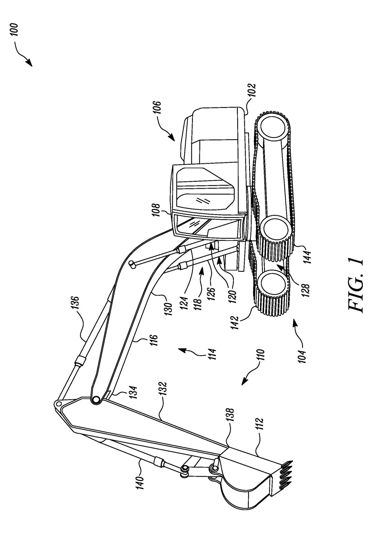
[0013]Referring to FIG. 1, a machine 100 is shown. The machine 100 may be an excavation machine, a hydraulic excavator, or a front shovel. The machine may embody other machine types having a linkage potential energy that could be a source for energy capture and reuse. The machine 100 may incorporate multiple systems, sub-systems, and components that cooperate to excavate and load earthen material onto a dumpsite. In addition, the machine 100 embodies a tracked configuration, as shown. Alternatively, the machine 100 may embody a wheeled configuration or a combination of a tracked and a wheeled configuration, as well. The machine 100 may also represent other types of earth-working units, such as wheel loaders, backhoe loaders, dragline excavators, cranes, skid steer loaders, or similar machines, which incorporate hydraulically operated systems to perform relatively heavy duty operations, such as those involving material transfer. In one example, the hydraulically operated systems may ...


PUM


Abstract

A fluid system for a machine that includes a linkage. The fluid system includes an actuator, an accumulator, a pilot circuit, and a pressure reducing valve. The actuator is configured to manipulate the linkage. The accumulator is configured to store a fluid discharged by the actuator under pressure. The pilot circuit is fluidly coupled to the accumulator and is configured to receive the fluid from the accumulator. Further, the pressure reducing valve is positioned between the accumulator and the pilot circuit to regulate the pressure of the fluid delivered to the pilot circuit from the accumulator.

Description

TECHNICAL FIELD[0001]The present disclosure relates to the field of energy recovery and reuse in fluid systems of machines. More particularly, the present disclosure relates to integrated energy recovery and reuse circuits of hydraulic systems associated with operations of linkages in machines.BACKGROUND[0002]Machines may be used to excavate portions of a worksite. Such machines include swing-type excavation machines, hydraulic excavators, front shovels, etc. Such machines generally include hydraulically powered implement systems or work tool assemblies that effectuate a material transfer operation. Such work tool assemblies commonly include an implement and one or more linkages, such as a boom, a stick, and / or lift arms, which may be suitably in turn powered by associated hydraulic circuits, as is customary. These circuits function in concert and require relatively significant hydraulic pressures to fulfill various parametric based operations, such as those involving raising, artic...

Claims


Application Information

Patent Timeline
IPC IPC(8): F15B11/024F04D13/04F15B1/02F15B1/04F15B1/027
CPCF15B11/024F15B1/04F04D13/04F15B1/024F15B1/027F01P7/044F15B21/14F15B2211/20569F15B2211/20576F15B2211/212F15B2211/50554F15B2211/7142F01P5/04
Inventor SHANG, TONGLINEGELJA, ALEKSANDARPATEL, KALPESHZHANG, JIAOMA, PENGFEICHEN, DAYAO
Owner CATERPILLAR INC
Why Eureka
Try Eureka