Electric Vehicle

Active Publication Date: 2013-07-04
KAWASAKI MOTORS LTD
View PDF2 Cites 14 Cited by
  • Summary
  • Abstract
  • Description
  • Claims
  • Application Information

AI Technical Summary

Benefits of technology

[0007]The present invention addresses the above described condition, and an object of the present invention is to reco

Problems solved by technology

Because of this, if the driver depresses the brake pedal, the kinetic energy of the electric vehicle cannot be recove

Method used


Image

  • Electric Vehicle
  • Electric Vehicle
  • Electric Vehicle

Examples


Embodiment Construction

[0019]Hereinafter, an embodiment of the present invention will be described with reference to the drawings. Throughout the drawings, the same or corresponding components are identified by the same reference numerals and will not be described in repetition. The stated directions are referenced from the perspective of a driver riding in the electric vehicle.

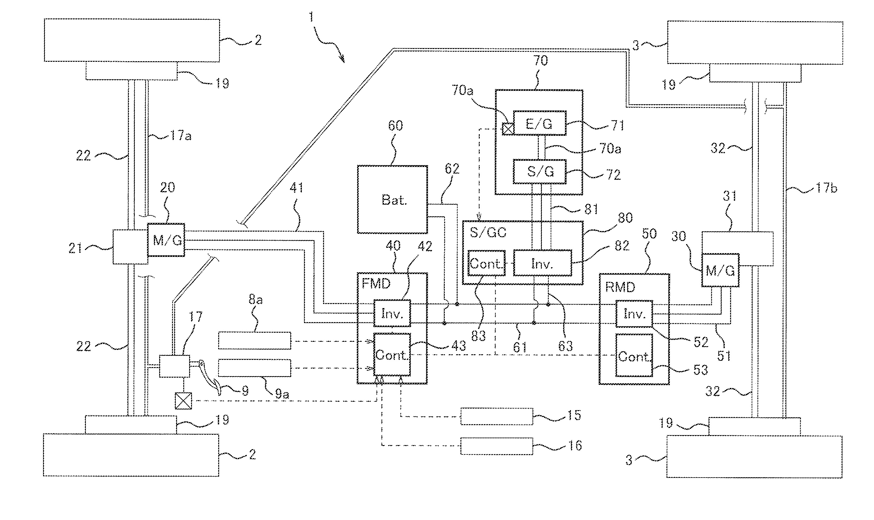
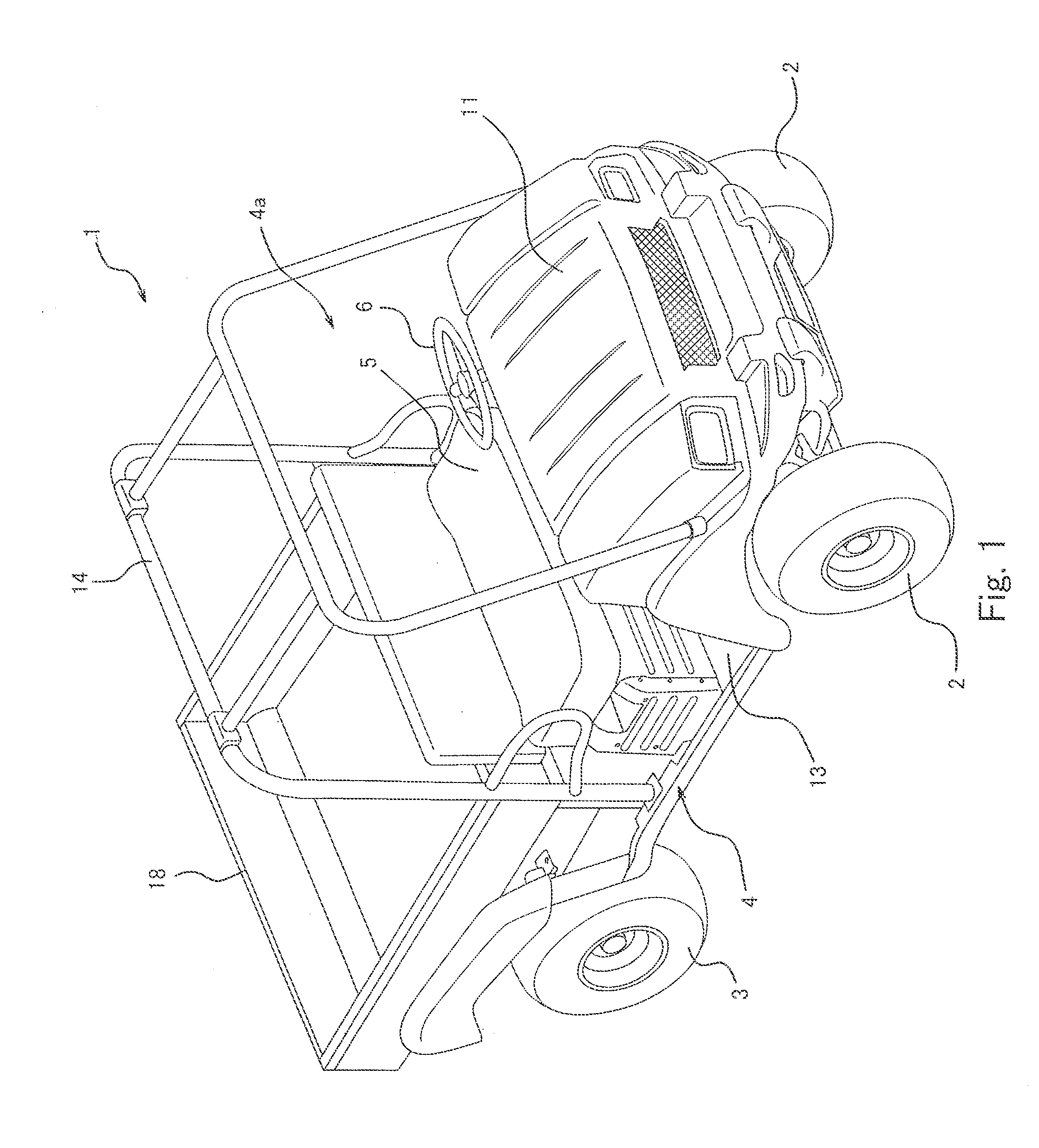
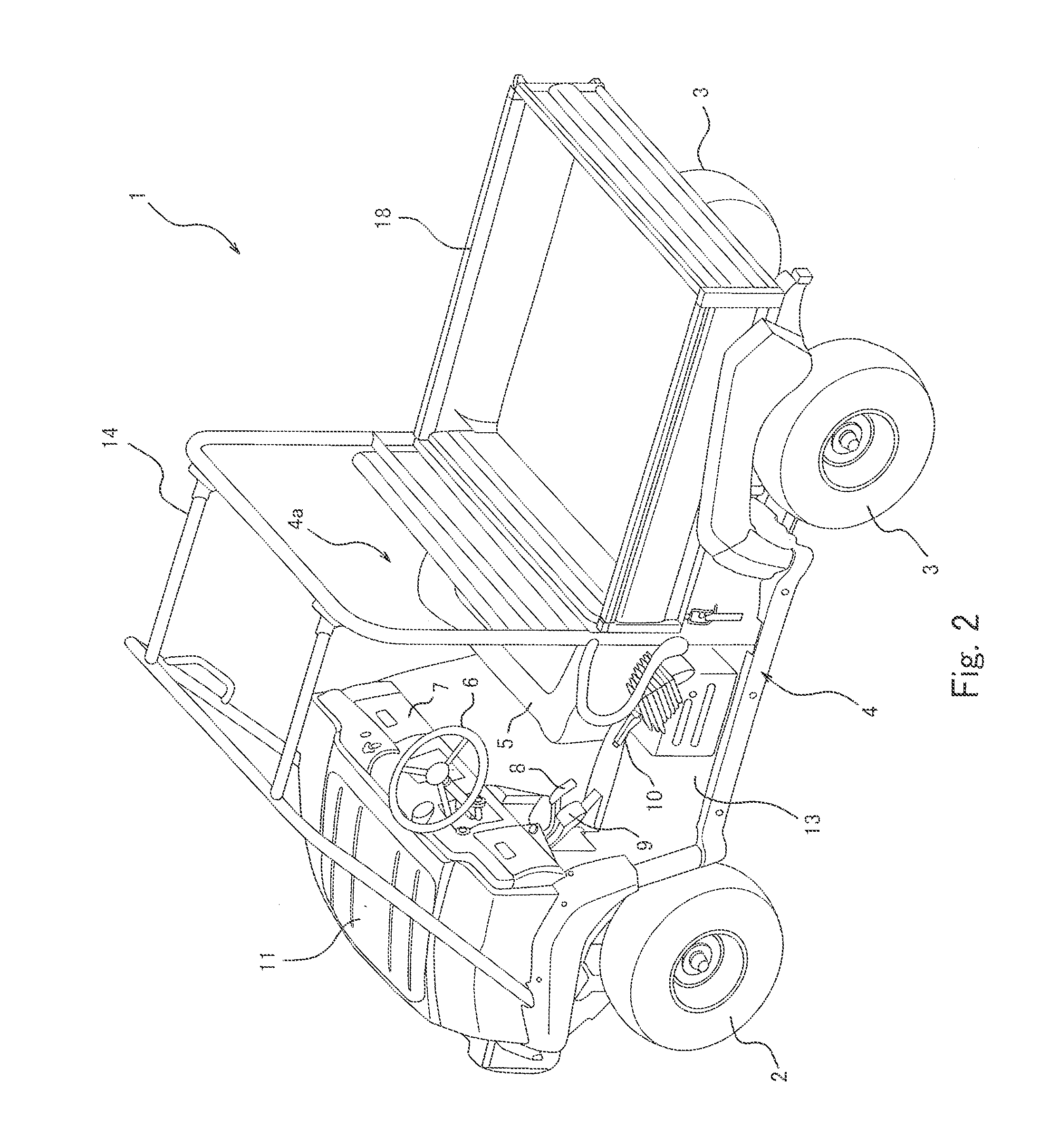
[0020]FIGS. 1 and 2 are perspective views of an external appearance of a utility vehicle 1 which is an embodiment of the electric vehicle according to the present invention. FIG. 3 is a block diagram schematically showing a drive control system in the utility vehicle 1. Referring to FIGS. 1 and 2, the utility vehicle 1 includes right and left front wheels 2 attached with balloon tires (low-pressure tires), right and left rear wheels 3 attached with balloon tires (low-pressure tires), and a vehicle body 4 from which the wheels 2 and 3 are suspended. A cabin space 4a for passengers is provided in a center portion of the vehicle body ...


PUM


Abstract

An electric vehicle is provided. The electric vehicle may include a motor for driving a wheel; a brake device for braking the wheel in response to a driver's operation of a brake operation member; and a controller for controlling the motor in response to the driver's operation of an accelerator operation member. The controller may include a first motor control section for causing the motor to be placed in a regenerative braking mode to generate a first regenerative braking force, when a displacement amount of the accelerator operation member decreases to an amount less than a predetermined reference displacement amount; and a second motor control section for causing the motor to generate a second regenerative braking force which is a sum of the first regenerative braking force and a predetermined additional braking force, in response to the operation of the brake operation member.

Description

BACKGROUND OF THE INVENTION[0001]1. Field of the Invention[0002]The present invention generally relates to an electric vehicle including an electric motor as a driving power source. Particularly, the present invention relates to regenerative braking control during deceleration of the electric vehicle.[0003]2. Description of the Related Art[0004]Conventionally, in an electric vehicle including an electric motor as a driving power source, during deceleration, the motor is actuated by a force applied by wheels. Thereby, the motor generates a braking force to be applied to the wheels, and operates as an electric generator to charge a battery. This operation is generally referred to as regenerative braking, in which kinetic energy of the vehicle is converted into electric energy. In this way, the kinetic energy is recovered.[0005]For example, Japanese Laid-Open Patent Application Publication No. Hei. 05-191904 discloses a technique in which a regenerative braking force corresponding to a...

Claims


Application Information

Patent Timeline
IPC IPC(8): B60W10/08B60W30/18B60W10/192
CPCB60W10/08B60K6/46B60K6/52B60W30/18127Y02T10/6265B60W2540/12B60W20/1062Y02T10/6217B60W2540/103B60W20/14Y02T10/62
Inventor TAKAGI, IZUMI
Owner KAWASAKI MOTORS LTD
Why Eureka
Try Eureka