Logic input device with energy recovery for an industrial automatic control system

a technology of automatic control system and input device, which is applied in the direction of ac-dc conversion, electrical variable regulation, programme control, etc., can solve the problems of loss of electrical power of vehicles, and achieve the effect of reducing heat dissipation and saving electrical energy

Inactive Publication Date: 2002-06-25
SOPRANO
View PDF6 Cites 14 Cited by
  • Summary
  • Abstract
  • Description
  • Claims
  • Application Information

AI Technical Summary

Benefits of technology

The object of the invention is to achieve a logic input device with reduced heating and with electrical energy recovery.
The heat dissipation is thus reduced enabling the use of heat sinks to be avoided, resulting in addition in a saving of electrical energy due to the effect of energy restoration to the battery.

Problems solved by technology

The problem arising in conventional equipment is then that of heat dissipation in the measuring resistors, for a logic input at a voltage of 110 Volts for example, and with a current intensity of 10 mA, will dissipate a thermal power of 1.1 W. The global heat dissipation is naturally proportional to the number of logic inputs and often requires the use of cooling devices by heat sink or heat pipes to dissipate the heat to the outside.
The electrical power supply of the equipment being performed from a safety power system with a backup battery bank, this results in addition in a loss of electrical power of the vehicle.

Method used


Image

  • Logic input device with energy recovery for an industrial automatic control system
  • Logic input device with energy recovery for an industrial automatic control system
  • Logic input device with energy recovery for an industrial automatic control system

Examples


Embodiment Construction

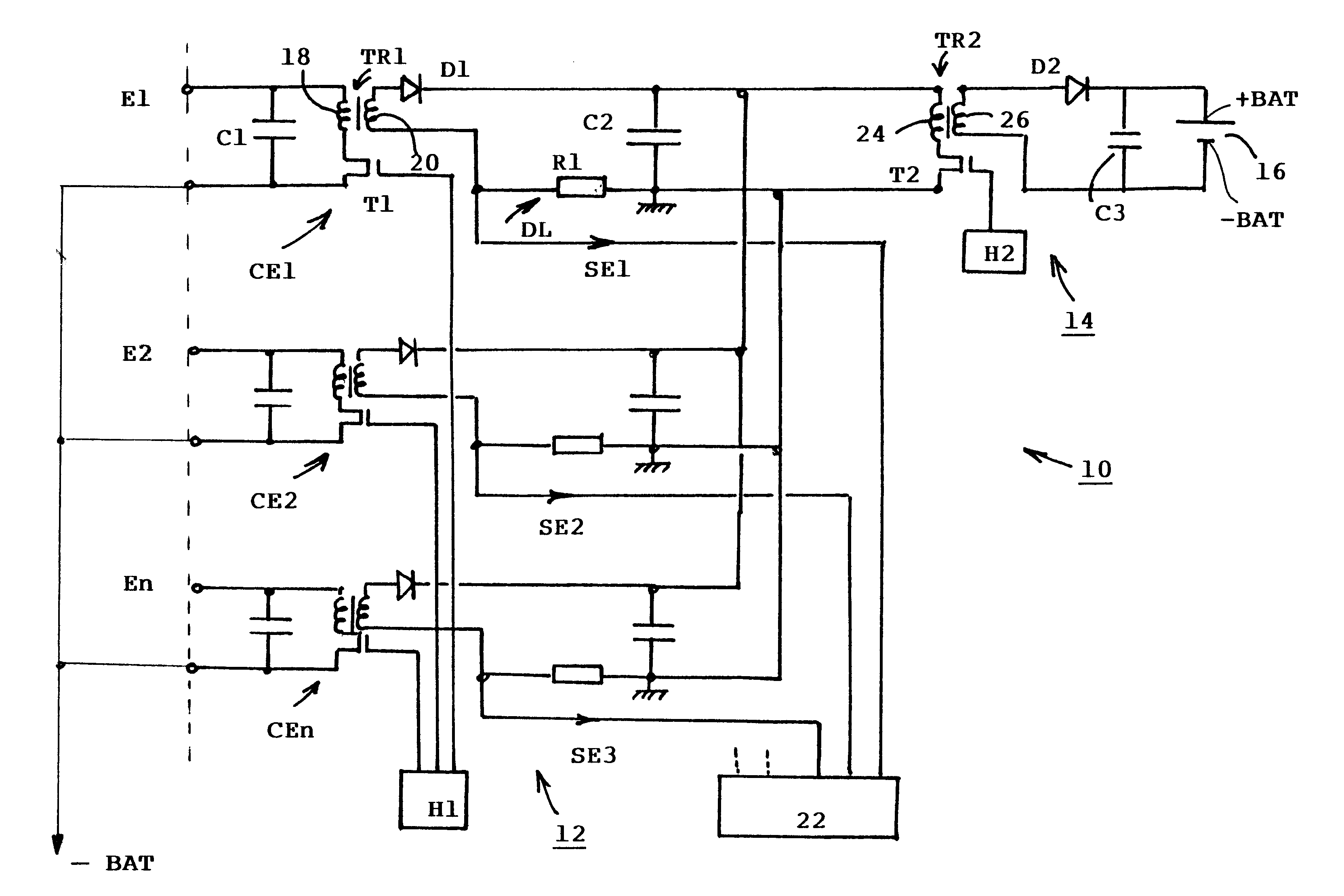
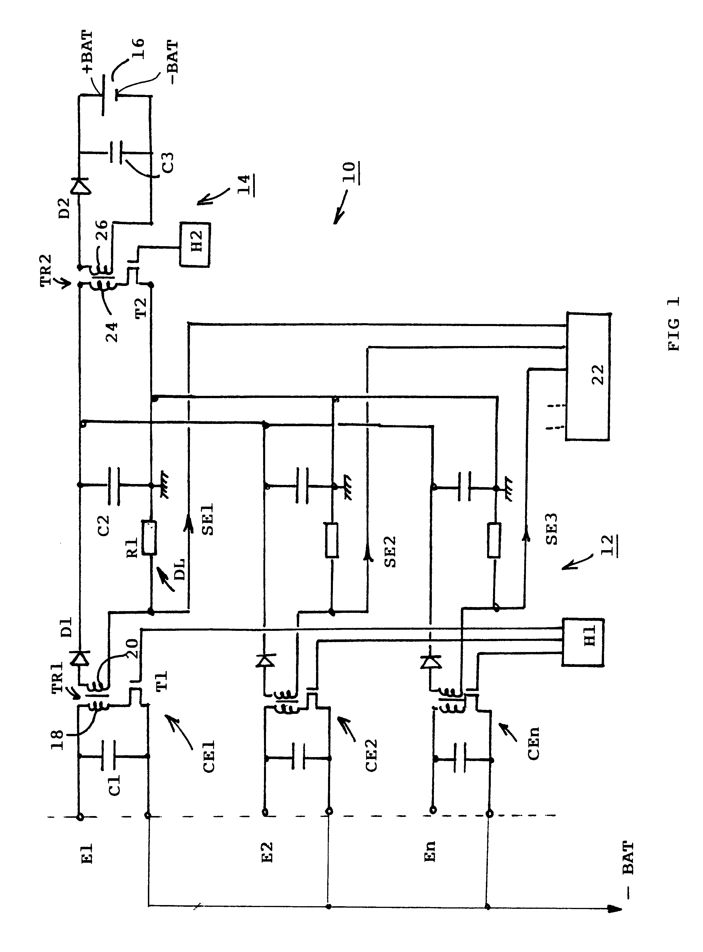
In FIG. 1, a logic input device 10 of an electronic equipment unit for an industrial automatic control system comprises a first detection stage 12 having a plurality of input circuits CE1, CE2, . . . CEn, and a second energy recovery stage 14 connected to a battery 16 or another DC supply having a positive pole +BAT and a negative pole -BAT.

The elementary input circuits CE1, CE2, . . . CEn of the first detection stage 12 are all identical to one another and are respectively connected to the inputs E1, E2, . . . En of the electronic equipment. The input circuits CE1, CE2, . . . CEn are also connected in parallel to the input of the common second energy recovery stage 14. In the following, only the input circuit CE1 of the first detection stage 12 will be described in detail.

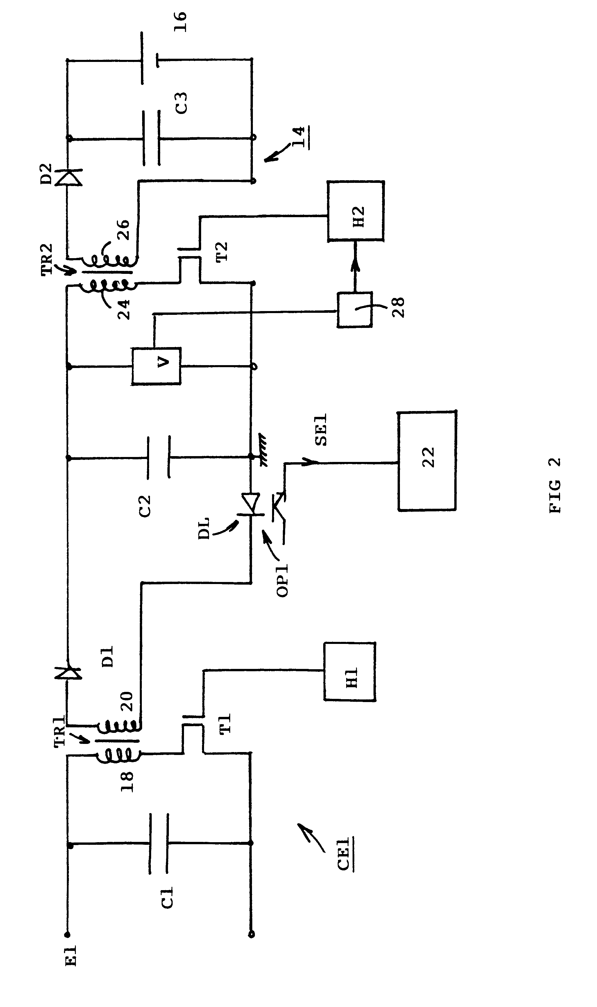
The input circuit CE1 comprises a first transformer TR1 having a primary winding 18 connected to the input E1 by means of a first chopping transistor T1. A filtering capacitor C1 is connected in parallel to the te...


PUM


Abstract

An electronic equipment for onboard process control includes a first detection stage with a plurality input circuits, comprising each a first transformer having a primary coil connected to the corresponding input via a first hashing transistor, and a secondary coil connected to a diode rectifier circuit. A first clock sends control signals to the first hashing transistor. Adjusting means cooperate with the first clock for adjusting the frequency of the control signals or the cyclic ratio for adapting the voltage of said input circuit. A logic level detector is inserted in the secondary circuit of the first transformer, and is electrically connected to an acquisition circuit. A second recovery stage is connected to a battery supplying the equipment for restoring the energy drained by the input circuits of the first detection stage.

Description

The invention relates to a logic input device of an electronic equipment for an industrial automatic control system comprising a first detection stage having a plurality of input circuits and an acquisition circuit for acquisition of the input signals detected by said input circuits.STATE OF THE TECHNIQUEThe logic input function implemented in electronic equipment for automatic control systems of on-board installations, in particular of rail transport vehicles, generally requires a large current in the logic inputs. The problem arising in conventional equipment is then that of heat dissipation in the measuring resistors, for a logic input at a voltage of 110 Volts for example, and with a current intensity of 10 mA, will dissipate a thermal power of 1.1 W. The global heat dissipation is naturally proportional to the number of logic inputs and often requires the use of cooling devices by heat sink or heat pipes to dissipate the heat to the outside. The electrical power supply of the e...

Claims


Application Information

Patent Timeline
Patent Type & Authority Patents(United States)
IPC IPC(8): G05B19/042G05B19/04G05B19/05H01H9/16
CPCG05B19/0423G05B19/054H01H9/167
Inventor PIRON, PATRICK
Owner SOPRANO
Why Eureka
Try Eureka