Integrated enhanced oil recovery process

a technology of enhanced oil and oil reservoir, applied in the direction of liquefaction, lighting and heating equipment, borehole/well accessories, etc., can solve the problems of limited availability of cosub>2/sub>, dwindling production, and natural pressure drop of oil reservoirs, etc., and achieve the effect of improving oil recovery

Active Publication Date: 2011-04-21
SURE CHAMPION INVESTMENT LTD
View PDF99 Cites 121 Cited by
  • Summary
  • Abstract
  • Description
  • Claims
  • Application Information

AI Technical Summary

Benefits of technology

[0016](1) injecting a pressurized carbon dioxide stream into an underground hydrocarbon reservoir to enhance production of the hydrocarbon-containing fluid from the underground hydrocarbon reservoir via a hydrocarbon production well, the hydrocarbon-containing fluid comprising carbon dioxide;
[0034](B) a carbon dioxide injection well in fluid communication with an underground hydrocarbon reservoir, the carbon dioxide injection well adapted to inject a pressurized carbon dioxide stream into the underground hydrocarbon reservoir for enhanced oil recovery;

Problems solved by technology

After some period of production, the natural pressure of the oil reservoir decreases and production dwindles.
One difficulty with the use of CO2 to increase oil production is that it requires large quantities of CO2, and the availability of such large quantities of CO2 is limited.
CO2 from natural sources can be utilized, but generally requires the natural source to be in the proximity of the oil reservoir to avoid the construction and use of pipelines, which could make such use uneconomical.
Use of CO2 from combustion sources (such as power plants) has also been considered (see, for example, U.S. Pat. No. 7,299,868 and publications cited therein), but the separation of CO2 from the combustion gases is difficult and generally not considered economical.
A disadvantage in this operation is the pipeline, as supercritical CO2 is considered a hazardous material.
The construction, permitting, operation and maintenance of a supercritical CO2 pipeline, particularly one as long as 205 miles, is expensive.
Another disadvantage to the use of CO2 for EOR is that, as more CO2 is pumped into an oil reservoir, more CO2 is also produced along with the other liquids and gases that come out of the well.
Traditionally, CO2 that is co-produced with oil is separated and vented to the atmosphere; however, as with synthesis gas production operations, environmental concerns make this CO2 venting undesirable.

Method used


Image

  • Integrated enhanced oil recovery process
  • Integrated enhanced oil recovery process
  • Integrated enhanced oil recovery process

Examples


examples of specific embodiments

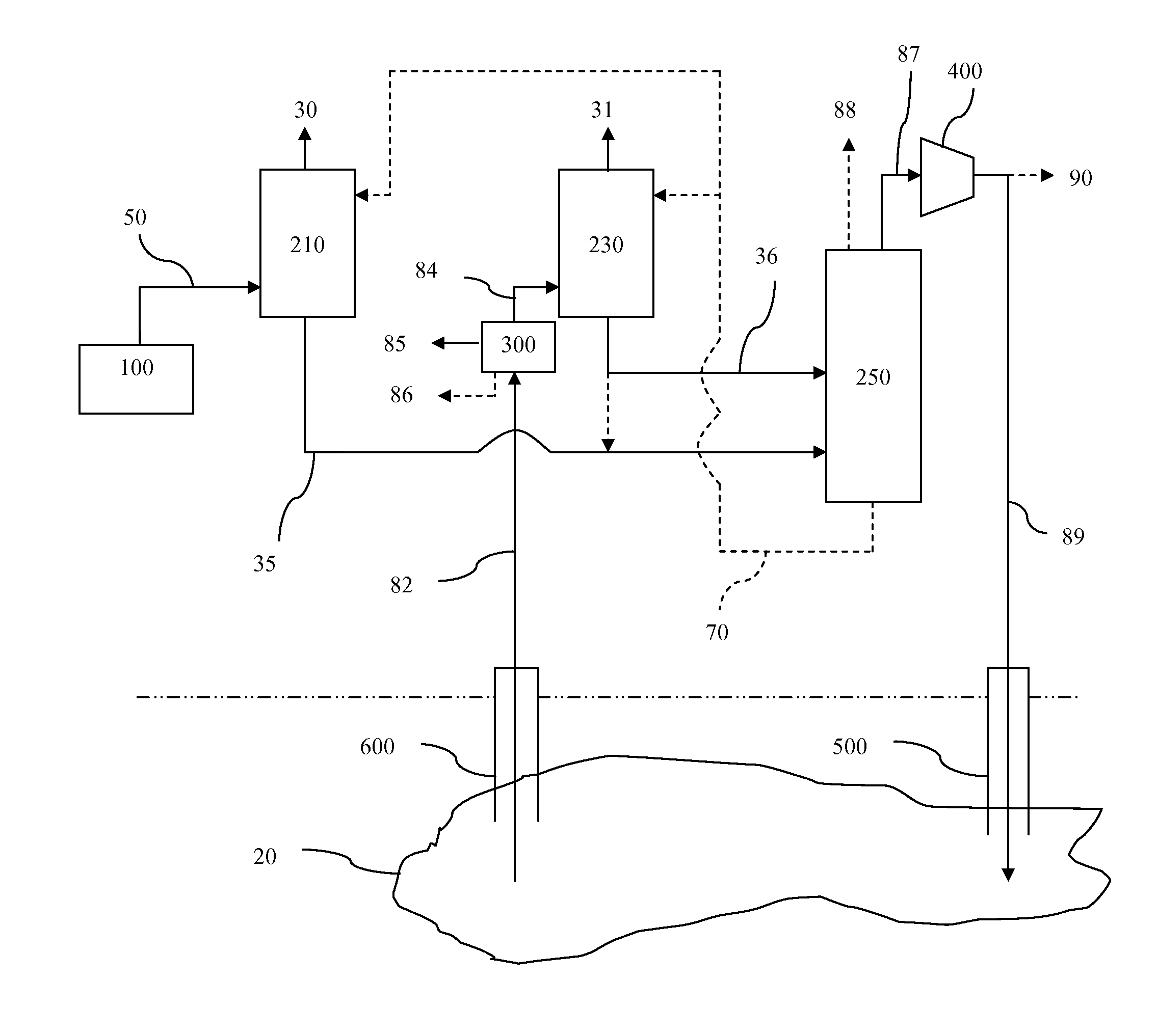
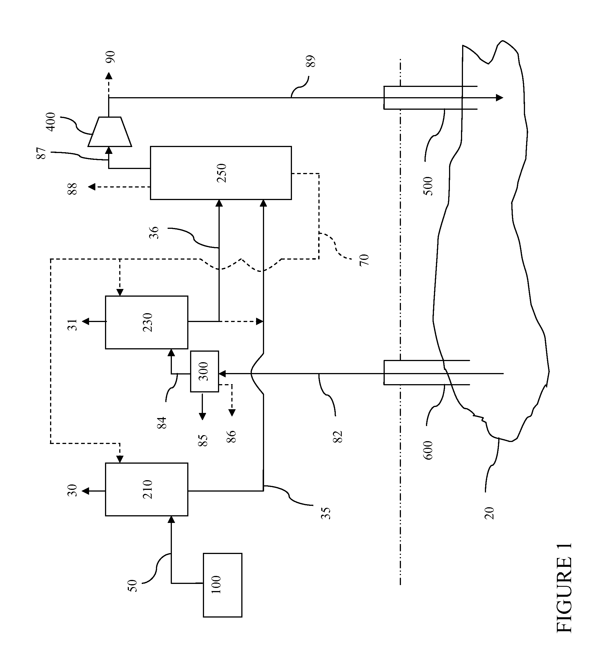
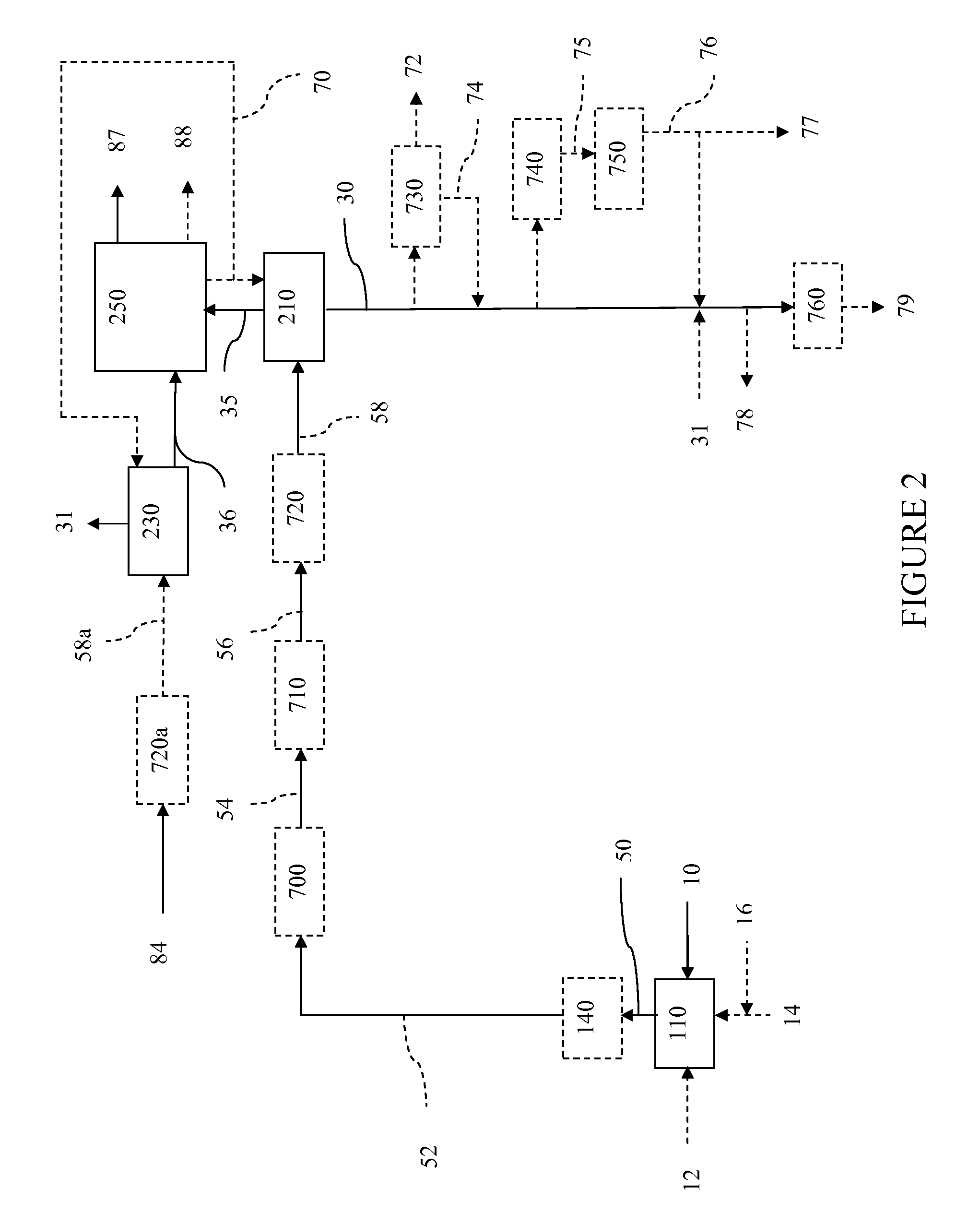
[0170]In one embodiment, the synthesis gas stream is produced by a catalytic steam methane reforming process utilizing a methane-containing stream as the carbonaceous feedstock.

[0171]In another embodiment, the synthesis gas stream is produced by a non-catalytic (thermal) gaseous partial oxidation process utilizing a methane-containing stream as the carbonaceous feedstock.

[0172]In another embodiment, the synthesis gas stream is produced by a catalytic autothermal reforming process utilizing a methane-containing stream as the carbonaceous feedstock.

[0173]The methane-containing stream for use in these processes may be a natural gas stream, a synthetic natural gas stream or a combination thereof. In one embodiment, the methane-containing stream comprises all or a portion of the acid gas-depleted gaseous hydrocarbon product stream, the acid gas-depleted synthesis gas stream, a combination of these streams, and / or a derivative of one or both of these streams after downstream processing.

[0...


PUM


Abstract

The present invention relates to an enhanced oil recovery process that is integrated with a synthesis gas generation process, such as gasification or methane reforming, involving combined capture and recycle of carbon dioxide from both processes.

Description

CROSS REFERENCE TO RELATED APPLICATION[0001]This application claims priority under 35 U.S.C. §119 from U.S. Provisional Application Ser. No. 61 / 252,936 (filed 19 Oct. 2009), the disclosure of which is incorporated by reference herein for all purposes as if fully set forth.[0002]This application is related to commonly-owned U.S. Provisional application Ser. No. ______, (attorney docket no. FN-0055 US NP1, entitled INTEGRATED ENHANCED OIL RECOVERY PROCESS), filed concurrently herewith.FIELD OF THE INVENTION[0003]The present invention relates to an enhanced oil recovery process that is integrated with a synthesis gas generation process, such as gasification or reforming, involving combined capture and recycle of carbon dioxide from both processes.BACKGROUND OF THE INVENTION[0004]In view of dwindling supplies of crude oil, enhanced oil recovery (EOR) techniques are receiving renewed attention.[0005]Typically, oil is produced using the natural pressure of an oil reservoir to drive the cr...

Claims


Application Information

Patent Timeline
Patent Type & Authority Applications(United States)
IPC IPC(8): E21B43/00E21B43/22
CPCE21B43/164E21B43/40F25J3/0223F25J3/0233F25J3/0252Y02C10/12F25J2205/40F25J2205/50F25J2230/30F25J2230/80F25J2260/80F25J3/0266Y02P90/70Y02C20/40
Inventor RAMAN, PATTABHI K.
Owner SURE CHAMPION INVESTMENT LTD
Why Eureka
Try Eureka