

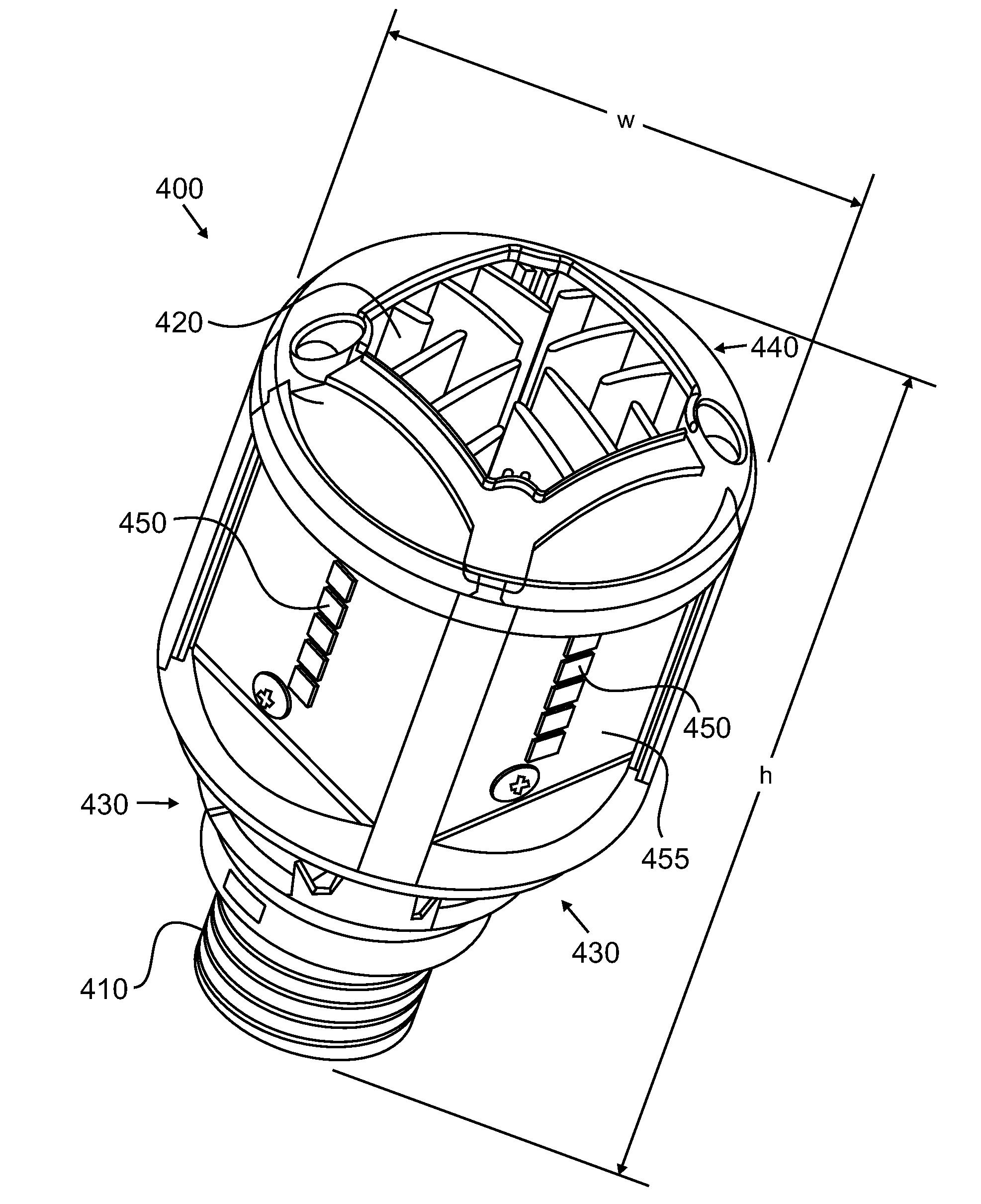
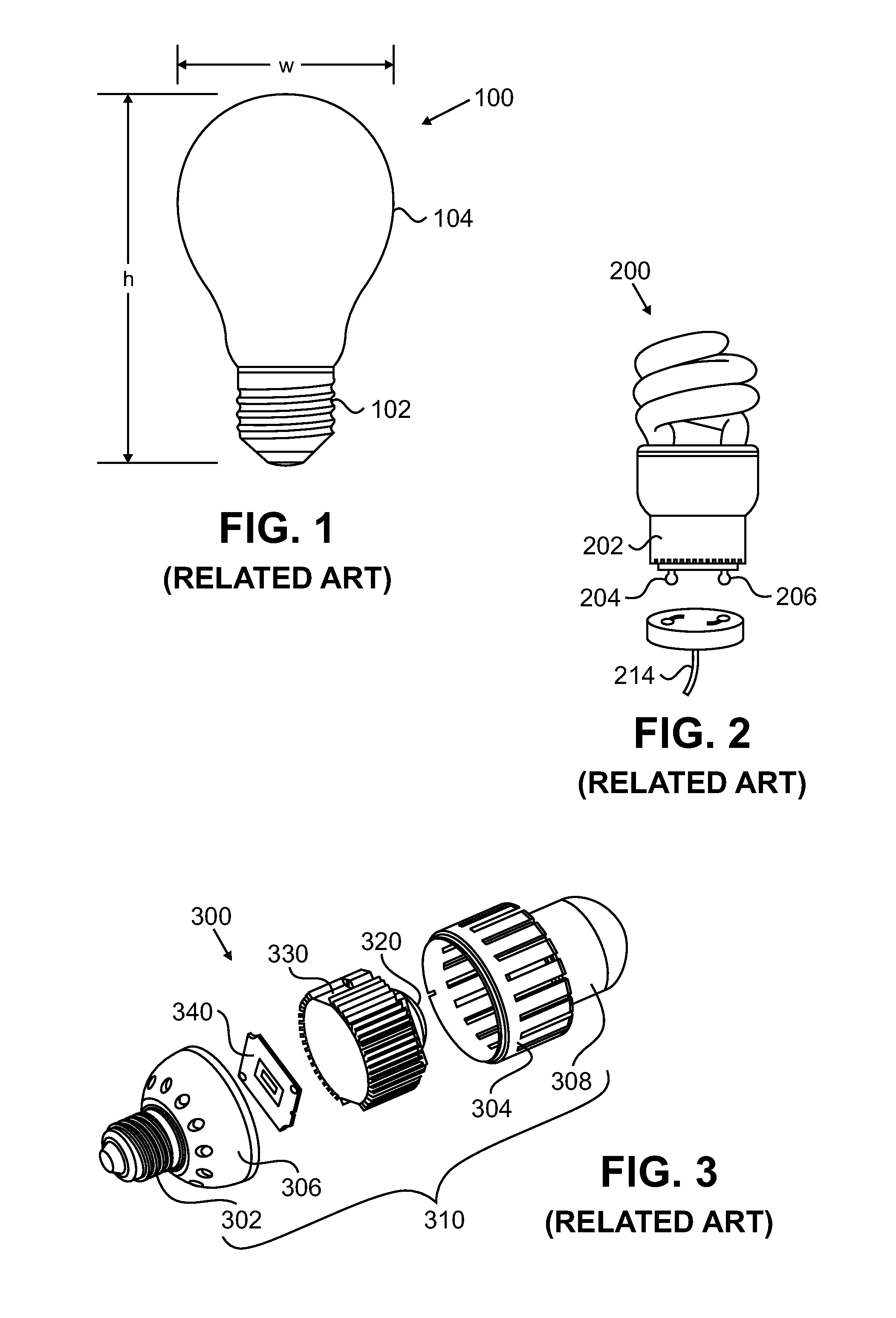
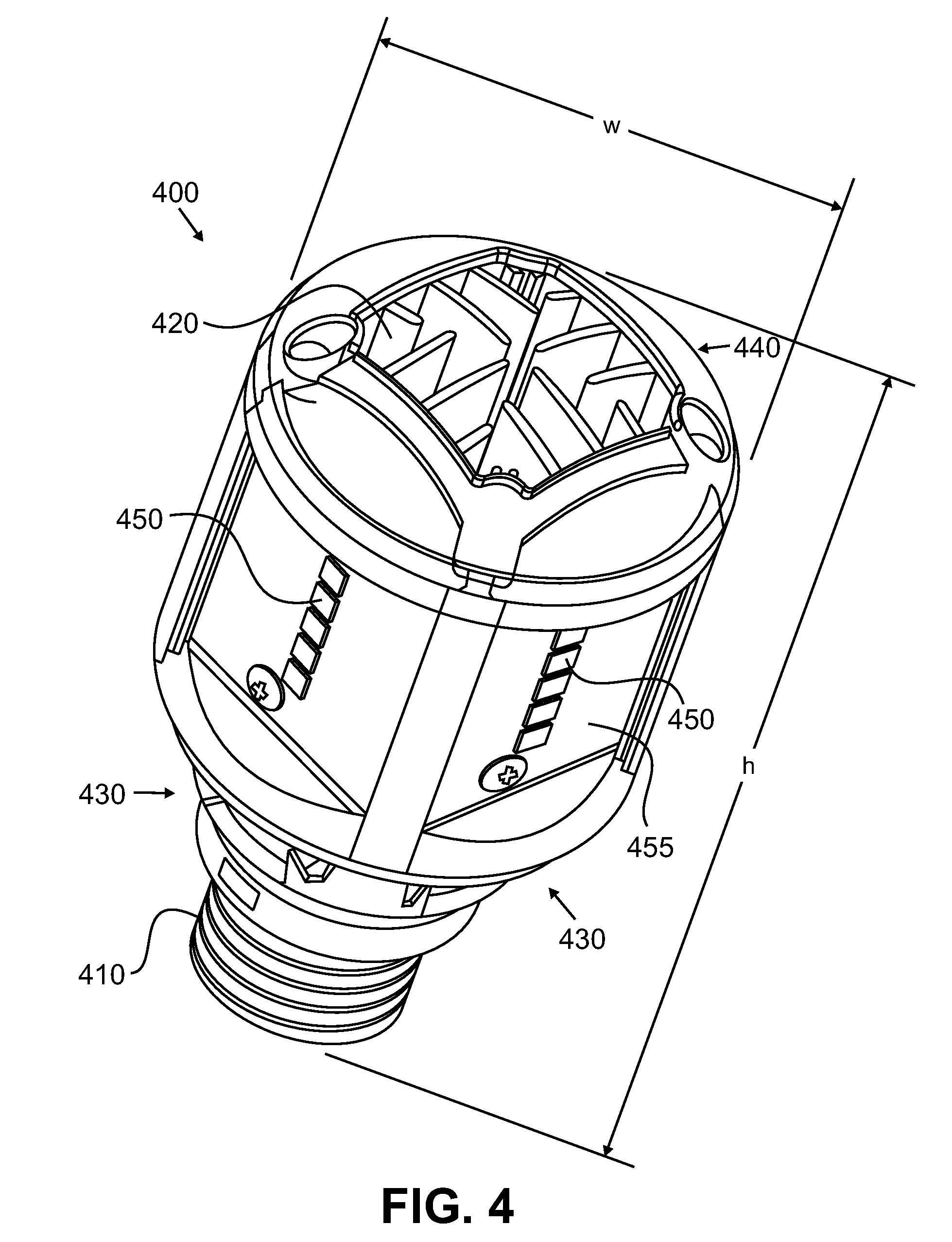
Compact Heat Sinks and Solid State Lamp Incorporating Same
a heat sink and compact technology, applied in the field of solid-state lamps, can solve the problems of reliability and lifetime, incandescent lamps are among the least energy-efficient designs in use, and achieve the effects of reliability and lifetim
- Summary
- Abstract
- Description
- Claims
- Application Information
AI Technical Summary
Benefits of technology
Problems solved by technology
Method used
Image

Examples
example
[0069]While not limited to the present example, a heat sink arrangement as illustrated in FIGS. 13 and 14 was produced from aluminum. The dimensions of the heat sink were as described above. Ten Cree XP LEDs (6 BSY and 4 red) from the R2 and M2 brightness bins were mounted on a MCPCB which was then mounted to the heat sink. A thermal grease was placed between the MCPCB and the heat sink to improve the thermal connection between the MCPCB and the heat sink. The lower section without a power supply was also constructed as part of the lenses.
[0070]The above described lamp was placed in the vertical orientation in a 25° C. ambient and driven with a remote power supply with 375 mA of current at 24.9 V initially and stabilized at 24.03 V after 40 minutes. The light output and electrical characteristics measured are summarized in Table 1 below.
TABLE 1Prototype A lamp test resultsTimeLumens XYCCTCRIVoltsWatts0905.50.4590.4126272692.324.939.35108050.47730.4146291492.6 24.189.07207820.44450.4...
PUM
 Abstract
Description
Claims
Application Information