Pipe clamp with self-aligning mechanism while closiing of same

a self-aligning and clamping technology, applied in the direction of hose connections, pipe joints, sleeves/socket joints, etc., can solve the problems of inability to achieve the desired lip alignment, components were too small, and the simple sounding requirement was surprisingly difficult to achieve in practi

Active Publication Date: 2011-04-28
KRAUSZ INDS DEVMENT
View PDF12 Cites 21 Cited by
  • Summary
  • Abstract
  • Description
  • Claims
  • Application Information

AI Technical Summary

Problems solved by technology

This simple-sounding requirement has however proved to be surprisingly difficult to achieve in practice.
On test it was found that the compone

Method used


Image

  • Pipe clamp with self-aligning mechanism while closiing of same
  • Pipe clamp with self-aligning mechanism while closiing of same
  • Pipe clamp with self-aligning mechanism while closiing of same

Examples


Embodiment Construction

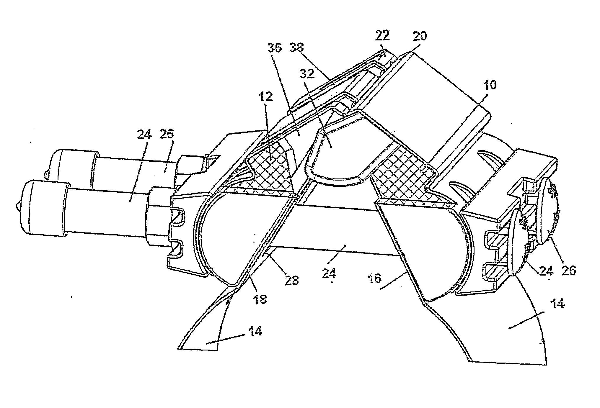
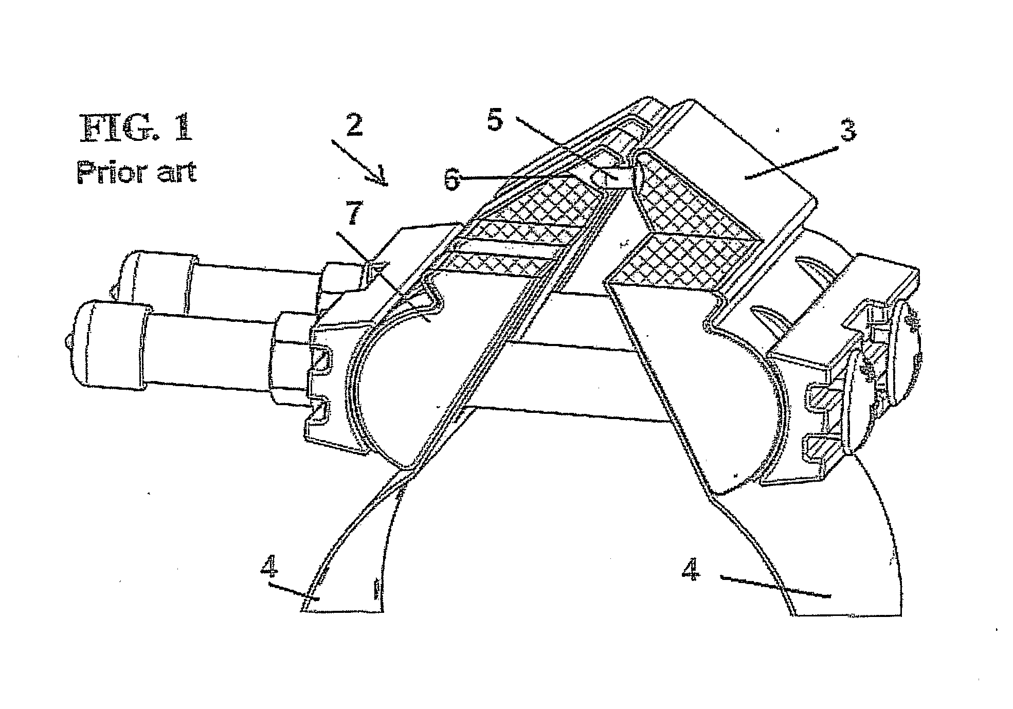
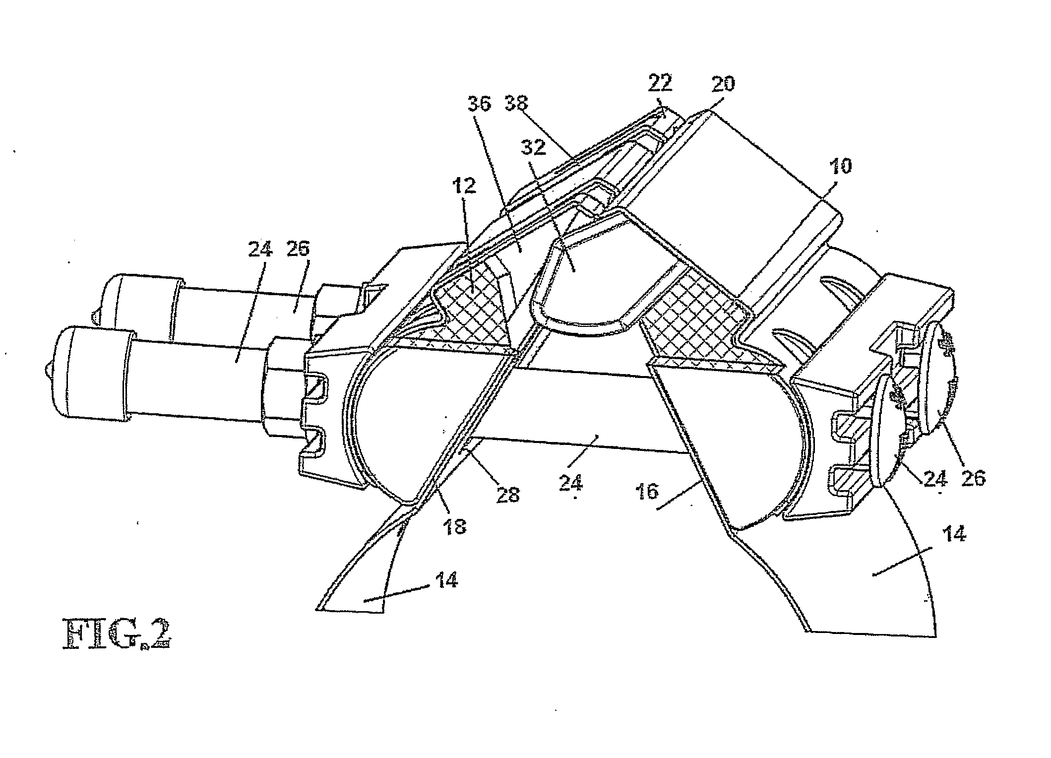
[0007]The present invention achieves the above object by providing a self-aligning means particularly useful in combination with a band pipe clamp or a band pipe coupling, said means comprising a first and a second rounded wedge-like shapes, the wedge base of the two shapes being disposed at an acute angle to each other when installed, the rounded wedge tips being in contact with each other, the metal band of said pipe coupling or clamp, when tightened by at least one screw fasteners reducing said acute angle between the bases of said wedge-like shapes, said wedge like position being provided with at least one aperture allowing passage for at least one screw fastener therethrough, said first rounded wedge-like shape being provided with at least one alignment projection, having a width of at least 20% of the base length, said projection extending from the wedge base surface of said first rounded wedge-like shape, and said second of said rounded wedge-like shapes being provided with a...


PUM


Abstract

The invention relates to a pipe clamp. The invention provides an improved external clamp for use on pipes, provided with a self-aligning mechanism. The self-aligning means is particularly useful in combination with a band pipe clamp or a band pipe coupling. The means comprising a first and a second rounded wedge-like shapes, the wedge base of the two shapes being disposed at an acute angle to each other when installed, the rounded wedge tips being in contact with each other, the metal band of the pipe coupling or clamp, when tightened by at least one screw fasteners reducing the acute angle between the bases of the wedge-like shapes. The wedge like position being provided with at least one aperture allowing passage for at least one screw fastener therethrough. The first wedge being provided with an alignment projection while the second wedge being provided with a complementary recess.

Description

FIELD AND BACKGROUND OF THE INVENTION[0001]The present invention relates to a pipe clamp.[0002]More particularly, the invention provides an improved external clamp for use on pipes, provided with a self-aligning mechanism.[0003]Pipes can be economically clamped or coupled by a metal band clamp. One of the advantages of his type of clamp is that it can be assembled to a pipeline even where no access is available to the pipe end. The present inventors have received patents for various types of band clamp, and production of said clamps has been commercially successful.[0004]The clamp in the prior, art is substantially wedge shaped with rounded corners. In order to clamp correctly the two extremities or lips of the clamp need to be in line contact, and not one beneath the other. This simple-sounding requirement has however proved to be surprisingly difficult to achieve in practice. No relevant prior art was found.[0005]In the course of engineering research carried out by the inventors s...

Claims


Application Information

Patent Timeline
IPC IPC(8): F16L25/00
CPCF16L21/065F16L33/04F16L21/005
Inventor KRAUSZ, ELIEZERCHIPROOT, AVI
Owner KRAUSZ INDS DEVMENT
Why Eureka
Try Eureka