Clip applying apparatus with angled jaw

a technology of applying apparatus and jaw, which is applied in the field of applying apparatus, can solve the problems of jaw structure and/or distal end of the body portion, and obstructing surgeon's view of the surgical si

Active Publication Date: 2014-12-02
COVIDIEN LP
View PDF512 Cites 128 Cited by
  • Summary
  • Abstract
  • Description
  • Claims
  • Application Information

AI Technical Summary

Problems solved by technology

One problem associated with known clip applying apparatus is obstructed visualization of the surgical site especially during endoscopic surgical procedures.
More specifically, the jaw structure and / or the distal end of the body portion obstructs the surgeon's view of the surgical site.

Method used


Image

  • Clip applying apparatus with angled jaw
  • Clip applying apparatus with angled jaw
  • Clip applying apparatus with angled jaw

Examples


Embodiment Construction

[0020]Preferred embodiments of the presently disclosed clip applying apparatus will now be described in detail with reference to the drawings, in which like reference numerals designate identical or corresponding elements in each of the several views.

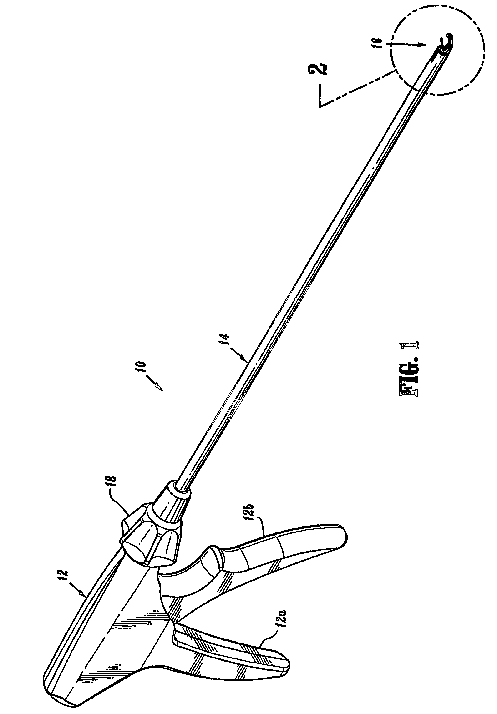
[0021]FIG. 1 illustrates one embodiment of the presently disclosed clip applying apparatus 10. Briefly, clip applying apparatus 10 includes a handle assembly 12 including a stationary handle 12a and a pivotable actuator trigger 12b, a central body portion 14 and a jaw mechanism 16. Although handle assembly 12 is illustrated having a pistol grip configuration other known handle configurations are envisioned, e.g., in-line handle, scissors handle, tweezers handle, etc. A rotatable knob 18 is rotatably supported on a distal end of handle assembly 12. Rotatable knob 18 supports the proximal end of central body portion 14 in a known manner such that rotatable knob 18, central body portion 14 and jaw mechanism 16 are rotatable in relation to ...


PUM


Abstract

A clip applying apparatus is provided which includes a jaw mechanism having a stationary jaw and a movable jaw. The movable jaw is supported on or formed integrally with the distal end of a crimping member which is movably supported within a body portion of the apparatus. The stationary jaw defines a longitudinal axis which forms an angle θ of between about 15 degrees and about 15 degrees and about 75 degrees in relation to a longitudinal axis of the body portion. In another embodiment, the stationary jaw includes a clip receiving channel which is configured to at least partially receive a surgical clip. In one embodiment, the distal end of the stationary jaw includes a stop member which is positioned to engage the distal end of the stationary jaw includes a stop member which is positioned to engage the distal end of a leg of a surgical clip to prevent the surgical clip from being pushed from the stationary jaw during operation of the apparatus and the movable jaw includes a distally located crimping surface and a head portion defining a recessed channel configured to receive a portion of a surgical clip supported on the stationary jaw. In yet another embodiment, the crimping surface defines an acute angle β in relation to the longitudinal axis of the body portion, and in one embodiment, angle β is substantially the same as angle θ.

Description

CROSS REFERENCE TO RELATED APPLICATIONS[0001]This application claims the benefit of and priority to International Application Serial No. PCT / US2004 / 007401 filed Mar. 11, 2004, which, in turn, claims the benefit of and priority to U.S. Provisional Application Ser. No. 60 / 453,581 filed on Mar. 11, 2003, entitled “CLIP APPLYING APPARATUS WITH ANGLED JAW”, and incorporates its entire contents by reference herein.BACKGROUND[0002]1. Technical Field[0003]The present disclosure relates to clip applying apparatus and ligation clips. More particularly, the present disclosure relates to clip applying apparatus for applying surgical clips to body tissue during surgical procedures which provide enhanced visibility at the surgical site.[0004]2. Background to Related Art[0005]Surgical procedures frequently require ligation of blood vessels, severed tissues and / or other organs to control or stop bleeding. Clip applying apparatus for quickly applying a surgical clip about tissue are well known. Such...

Claims


Application Information

Patent Timeline
Patent Type & Authority Patents(United States)
IPC IPC(8): A61B17/128A61B17/29A61B17/122A61B17/10A61B18/14A61B18/00
CPCA61B2018/00702A61B18/1445A61B2018/00875A61B17/1285A61B2018/0063A61B17/122A61B2018/00791A61B2017/2926
Inventor ARANYI, ERNESTWHITFIELD, KENNETH H.
Owner COVIDIEN LP
Why Eureka
Try Eureka