Single-stage zero-current switching driving circuit for ultrasonic motor

Active Publication Date: 2011-04-28
METAL INDS RES & DEV CENT
View PDF6 Cites 49 Cited by
  • Summary
  • Abstract
  • Description
  • Claims
  • Application Information

AI Technical Summary

Benefits of technology

[0022]The driving circuit according to the present invention integrates the buck-boost converter and the resonant inverter into a single-stage structure, so that the buck-boost converter and the resonant inverter share an active switch and a trigger signal, and therefore, the circuit is simplified and the loss caused by stage switching is reduced. Moreover, the buck-boost converter operates in a discontinuous-conduction mode (DCM), which allows the circuit to have high power factor, and enables the active switch to be capable of zero-current switching (ZCS), so that the loss caused by switching is largely redu

Problems solved by technology

The most disadvantage of this method is that the circuit is very complicated, the difficulty of controlling the circuit is

Method used


Image

  • Single-stage zero-current switching driving circuit for ultrasonic motor
  • Single-stage zero-current switching driving circuit for ultrasonic motor
  • Single-stage zero-current switching driving circuit for ultrasonic motor

Examples


Embodiment Construction

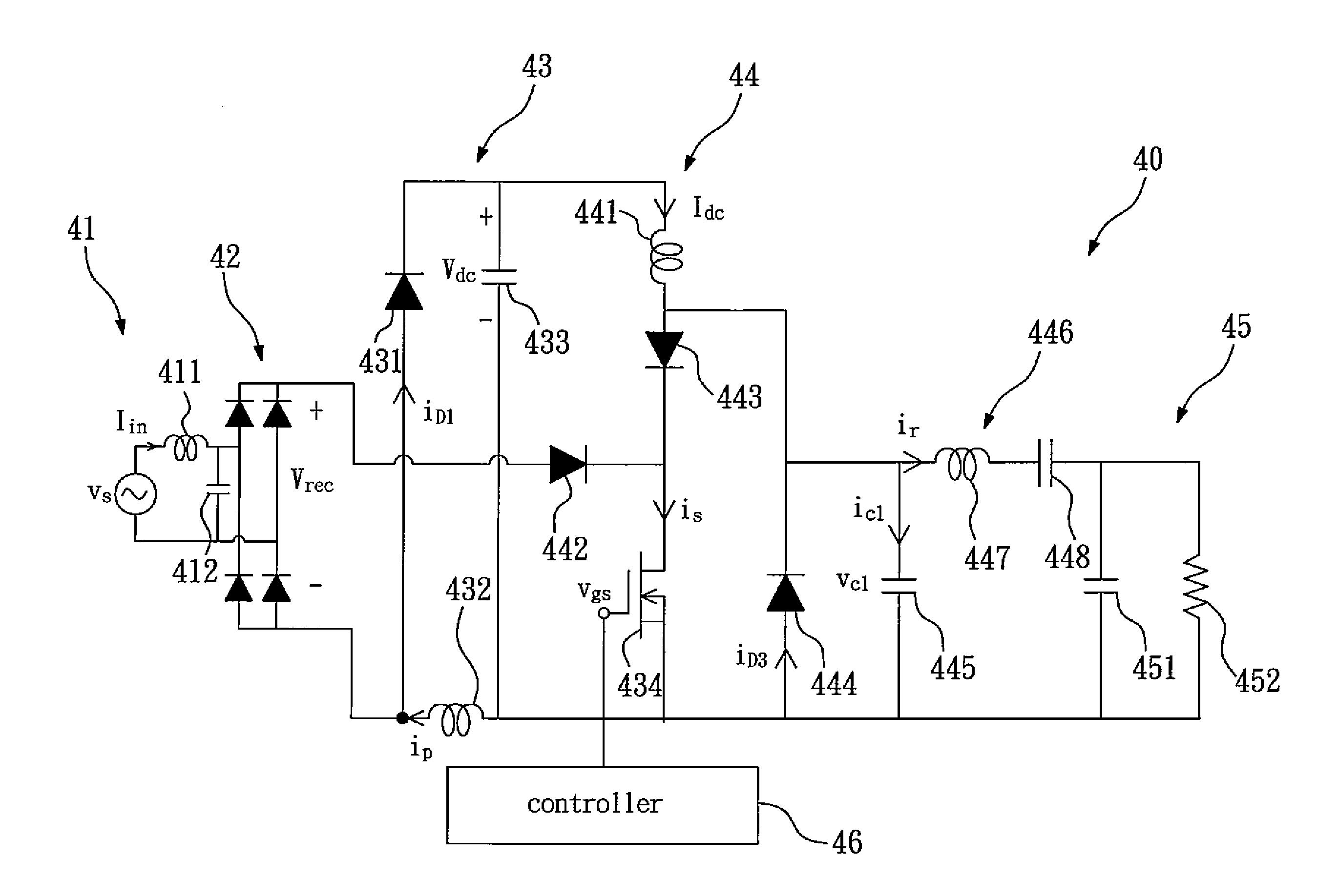
[0029]FIG. 4 shows a block diagram of a single-stage zero-current switching driving circuit for ultrasonic motor according to the present invention. FIG. 5 shows a circuit diagram of the single-stage zero-current switching driving circuit for ultrasonic motor according to the present invention. Referring to FIGS. 4 and 5, the single-stage zero-current switching driving circuit 40 for ultrasonic motor according to the present invention comprises: a low pass filter 41, a bridge rectifier 42, a buck-boost converter 43 and a zero-current switching resonant inverter 44. The low pass filter 41 comprises a filter inductor 411 and a filter capacitor 412, the bridge rectifier 42 comprises four rectifier diodes, the low pass filter 41 and the bridge rectifier 42 are used to filter and rectify an AC power source into a DC input power source (vrec), and the DC input power source is inputted into the buck-boost converter 43.

[0030]The buck-boost converter 43 receives the DC input power source (vr...


PUM


Abstract

The present invention relates to a single-stage zero-current switching driving circuit for ultrasonic motor, which comprises: a buck-boost converter and a zero-current switching resonant inverter. The driving circuit according to the present invention integrates the buck-boost converter and the resonant inverter into a single-stage structure, so that the buck-boost converter and the resonant inverter share an active switch and a trigger signal, and therefore, the circuit is simplified and the loss caused by stage switching is reduced. Moreover, the buck-boost converter operates in a discontinuous-conduction mode (DCM), which allows the circuit to have high power factor, and enables the active switch to be capable of zero-current switching (ZCS), so that the loss caused by switching is largely reduced. In the driving circuit according to the present invention, there's no interaction of power between the buck-boost converter and the resonant inverter, so that the two circuits can be analyzed individually. Therefore, the driving circuit according to the present invention having simplified circuit, low loss caused by switching, and low manufacturing cost, can be a competitive product after being commercialized.

Description

BACKGROUND OF THE INVENTION[0001]1. Field of the Invention[0002]The present invention relates to a single-stage zero-current switching driving circuit, and more particularly to a single-stage zero-current switching driving circuit for ultrasonic motor.[0003]2. Description of the Related Art[0004]FIG. 1 shows a circuit diagram of a conventional buck-boost power factor correction circuit. The conventional buck-boost power factor correction circuit 10 comprises a rectification circuit 11, an active switch 12, an inductor 13, a diode 14 and a capacitor 15. In which, the active switch 12 is a power device MOSFET (Metal-oxide-semiconductor Field-effect Transistor), and a control circuit 17 is used to generate a trigger signal (vgs) to drive the active switch 12 at high frequency. For achieving high power factor, the current of the inductor 13 is designed to operate in a discontinuous-conduction mode (DCM), and the switching frequency and the conduction rate of the active switch 12 are fix...

Claims


Application Information

Patent Timeline
IPC IPC(8): H02P31/00H01L41/00
CPCH02M1/4208Y02B70/126H02N2/008Y02B70/10
Inventor HSIEH, YAO-CHINGCHEN, CHENG-YENHONG, JIAN-YIHSUEH, PO-WEN
Owner METAL INDS RES & DEV CENT
Why Eureka
Try Eureka