Parallel link robot

a robot and parallel link technology, applied in the direction of mechanical control devices, process and machine control, instruments, etc., can solve the problems of decreasing the number of reciprocating operations per unit time, affecting the processing ability, and remarkably limited acceleration/deceleration performance of the moving plate 120/b>

Active Publication Date: 2011-04-28
FANUC LTD
View PDF1 Cites 65 Cited by
  • Summary
  • Abstract
  • Description
  • Claims
  • Application Information

AI Technical Summary

Benefits of technology

[0025]These and other objects, features and advantages of the present invention will be more apparent in light of the detailed description of exemplary embodiments thereof as illustrated by the drawings.

Problems solved by technology

Furthermore, in the configuration shown in FIG. 13, the actuator 130d is relatively heavy, so the movable plate 120 is remarkably limited in acceleration / deceleration performance.
For example, when the end effector of the parallel link robot 100 engages in simple reciprocating motion, the limited acceleration / deceleration performance results in the number of reciprocating operations per unit time decreasing and therefore the processing ability falling.
Due to the physical dimensions of the intermediate members 160, 170, this leads to further limitation of the possible region of operation of the movable plate 120.
For this reason, while increasing by a further two or three the degrees of freedom of the parallel link robot shown in FIG. 11 is theoretically possible, practical realization is difficult.
For this reason, in the prior art, there was the problem that the suction pad 780 became larger in size and more easily interfered with the workpiece W. Further, when using an end effector which cannot mount a rotation absorption unit 800 or when an electrical cable for the end effector is necessary, when driving the additional actuator 130d etc., there was also the problem that the piping relating to the end effector, for example, the air tubes, or wiring, for example, the electrical cables, would become wound around other members.

Method used


Image

  • Parallel link robot
  • Parallel link robot
  • Parallel link robot

Examples


Embodiment Construction

[0042]Below, embodiments of the present invention will be explained with reference to the attached drawings. In the following drawings, similar members are assigned similar reference numerals. To facilitate understanding, these drawings are suitably changed in scale.

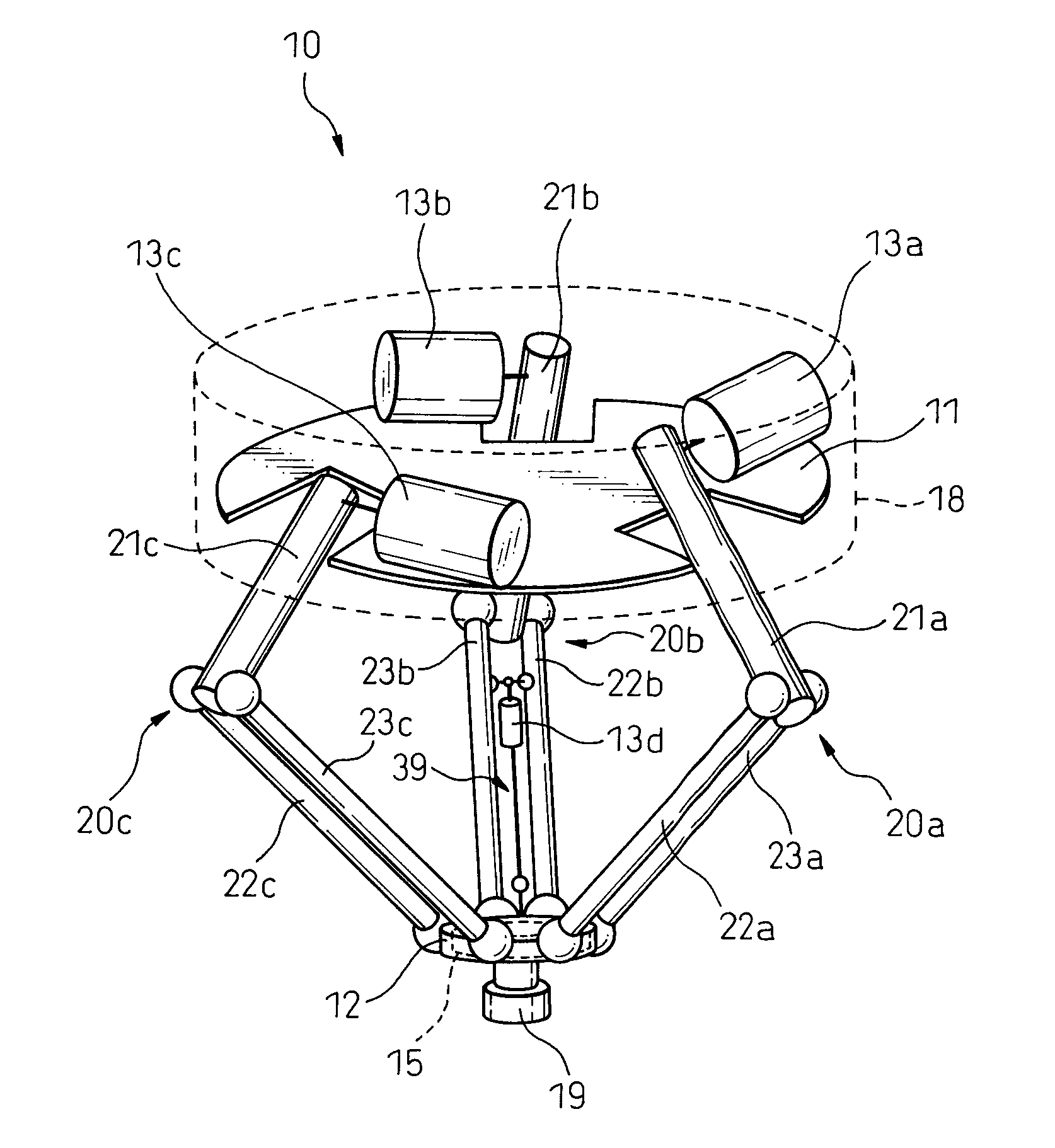
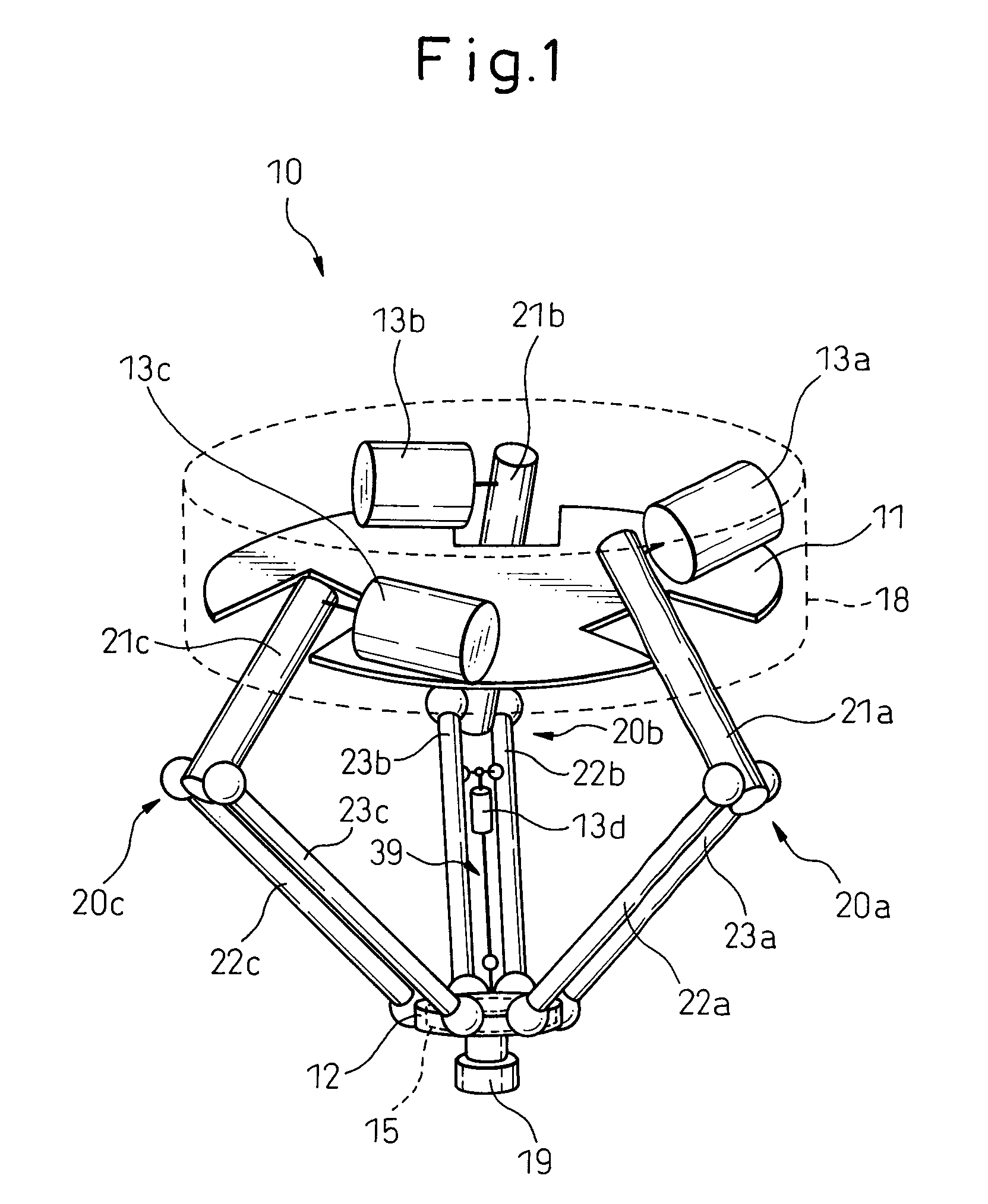
[0043]FIG. 1 is a perspective view of a parallel link robot in a typical embodiment based on the present invention. In FIG. 1, the parallel link robot 10 mainly includes a base 11 contained in a housing 18, a movable plate 12, and three links 20a to 20c coupling the base11 and movable plate 12. At the bottom surface of the movable plate 12, a mounting member 19 is provided. A not shown end effector is attached to the mounting member 19.

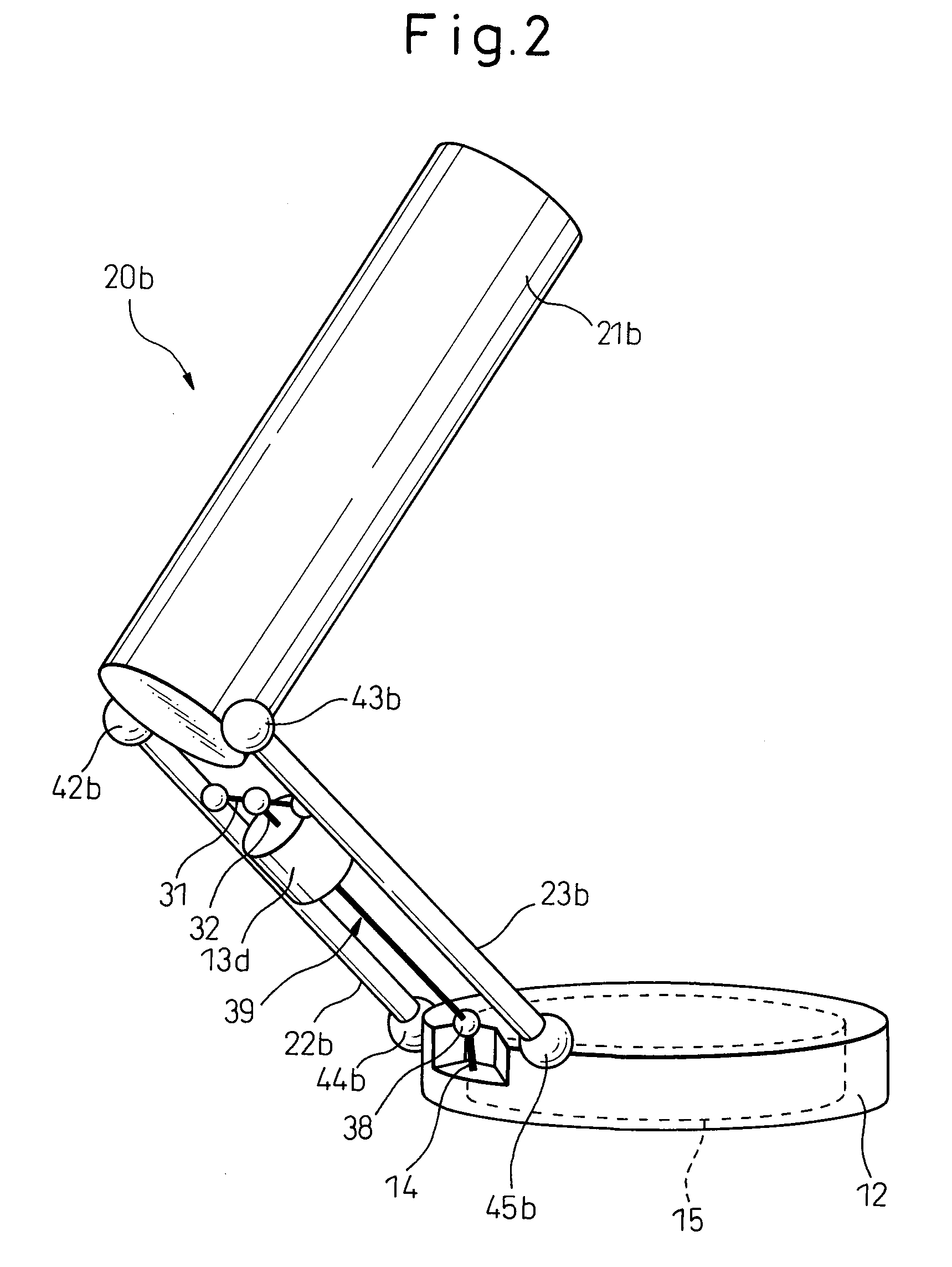
[0044]FIG. 2 is a partial perspective view of the parallel link robot shown in FIG. 1. As shown in FIG. 2, the link 20b is comprised of a drive link 21b and two driven links 22b, 23b extending from the movable plate 12. These are coupled together by spherical bearings 42b, 43b. Further, th...


PUM


Abstract

A parallel link robot (10) provided with a base (11), a moving part (12), three links (20a to 20c) coupling the base and the moving part and having respectively single degrees of freedom with respect to the base, and three actuators (13a to 13c) respectively driving the links, each of the links comprised of a drive link (21a to 21c) coupled with the base and two driven links (22a to 22c, 23a to 23c) coupling the drive link and the moving part and parallel to each other, and further provided with a posture changing mechanism (15) which changes a posture of an element (19) attached to the moving part, an additional actuator (13d to 13f) arranged between the two driven links of at least one link in parallel to these driven links, and a power transmission shaft (39) which extends coaxially from the additional actuator and transmits rotational drive force to the posture changing mechanism. Due to this, it is possible to increase the degrees of freedom without reducing the possible region of operation and the acceleration/deceleration performance.

Description

BACKGROUND OF THE INVENTION[0001]1. Field of the Invention[0002]The present invention relates to a parallel link robot using a delta type parallel link mechanism for positioning a mounting member equipped with an end effector three-dimensionally.[0003]2. Description of the Related Art[0004]FIG. 11 is a perspective view of a parallel link robot in the prior art. As shown in FIG. 11, the parallel link robot 100 of the prior art mainly includes a base 110, a movable plate 120, and three links 200a to 200c coupling the base 110 and movable plate 120. Note that, the movable plate 120 is provided with a mounting member 190 for a not shown end effector.[0005]As can be seen from FIG. 11, the link 200a is comprised of a drive link 210a extending from the base 110 and two driven links 220a, 230a extending from the movable plate 120. These are coupled with each other by spherical bearings. Further, the base 110 includes an actuator 130a driving the drive link 210a. Note that, the other links 2...

Claims


Application Information

Patent Timeline
Patent Type & Authority Applications(United States)
IPC IPC(8): B25J9/10
CPCB25J17/0266B25J9/0051Y10T74/20329Y10T74/20207Y10T74/20305
Inventor KINOSHITA, SATOSHINAGAYAMA, TOMOAKIYAMAMOTO, MASAHIROKUREBAYASHI, HIDENORIFUJIMOTO, KATSUMIUEMURA, TOKITAKA
Owner FANUC LTD
Why Eureka
Try Eureka