Manufacturing method and manufacturing apparatus for stator

a manufacturing apparatus and stator technology, applied in the direction of electrical equipment, manufacturing dynamo-electric machines, dynamo-electric machines, etc., can solve the problems of difficult to apply the method of disposing, difficult to dispose the coil in the stator core, and difficult to apply to the coil wound by distributed winding. , to achieve the effect of reducing the contact area between the restriction pieces and the straight portions, smooth disassembly and assembly, and relatively smooth movemen

Inactive Publication Date: 2011-05-05
AISIN AW CO LTD
View PDF6 Cites 16 Cited by
  • Summary
  • Abstract
  • Description
  • Claims
  • Application Information

AI Technical Summary

Benefits of technology

[0018]According to the invention of a ninth aspect, the contact portions of the restriction pieces are formed in a conical shape. Therefore, the contact area between the restriction pieces and the straight portions can be reduced, which allows the restriction jig and the coil to relatively move more smoothly.
[0019]According to the invention of a twelfth aspect, the circumferential positions of the straight portions can be restricted on the first-end side when disposing the coil in the insertion jig. Therefore, the restriction pieces can be smoothly disposed between the adjacent ones of the straight portions.

Problems solved by technology

JP-A-2003-153478 described above is a method for disposing a coil wound by concentrated winding in a stator core, and is difficult to apply to a coil wound by distributed winding.
Thus, because the two types of coils have different configurations, it is not easy to apply the method for disposing a coil wound by concentrated winding to a coil wound by distributed winding.
In particular, in the case where a rectangular wire with a rectangular cross section is used as a metal wire to form a coil, it is difficult to dispose the coil in a stator core compared to the case where a round wire with a circular cross section is used, because the rectangular wire has directional property for insertion into slots.
Therefore, in the case where a rectangular wire is to be disposed in slots by distributed winding, it is necessary to consider the directional property of the rectangular wire, which makes the work of disposing the wire difficult.
However, such work may be time-consuming and may increase the production cost.
It is difficult to form a coil into shape by distributed winding in advance and thereafter manually dispose the straight portions in a stator core from a radial direction, because it is necessary to elastically deform the continuous portions to a greater degree.
In particular, in the case where the coil is formed by a rectangular wire, the coil has a high rigidity and thus is difficult to elastically deform.
However, it is more difficult to manually dispose a coil with such a structure in a stator core as described above, because the presence of the folded portions makes elastic deformation more difficult.

Method used


Image

  • Manufacturing method and manufacturing apparatus for stator
  • Manufacturing method and manufacturing apparatus for stator
  • Manufacturing method and manufacturing apparatus for stator

Examples


Embodiment Construction

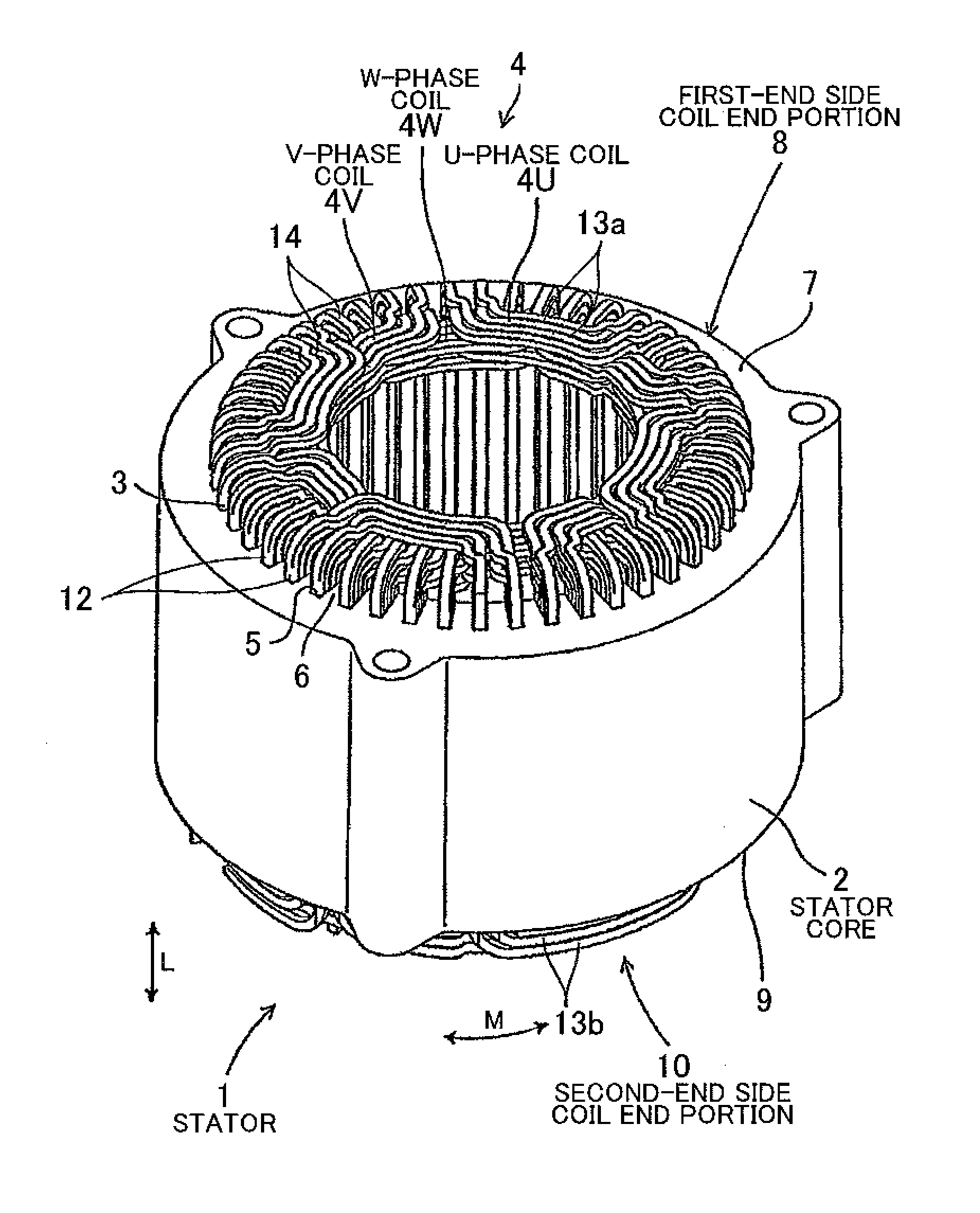
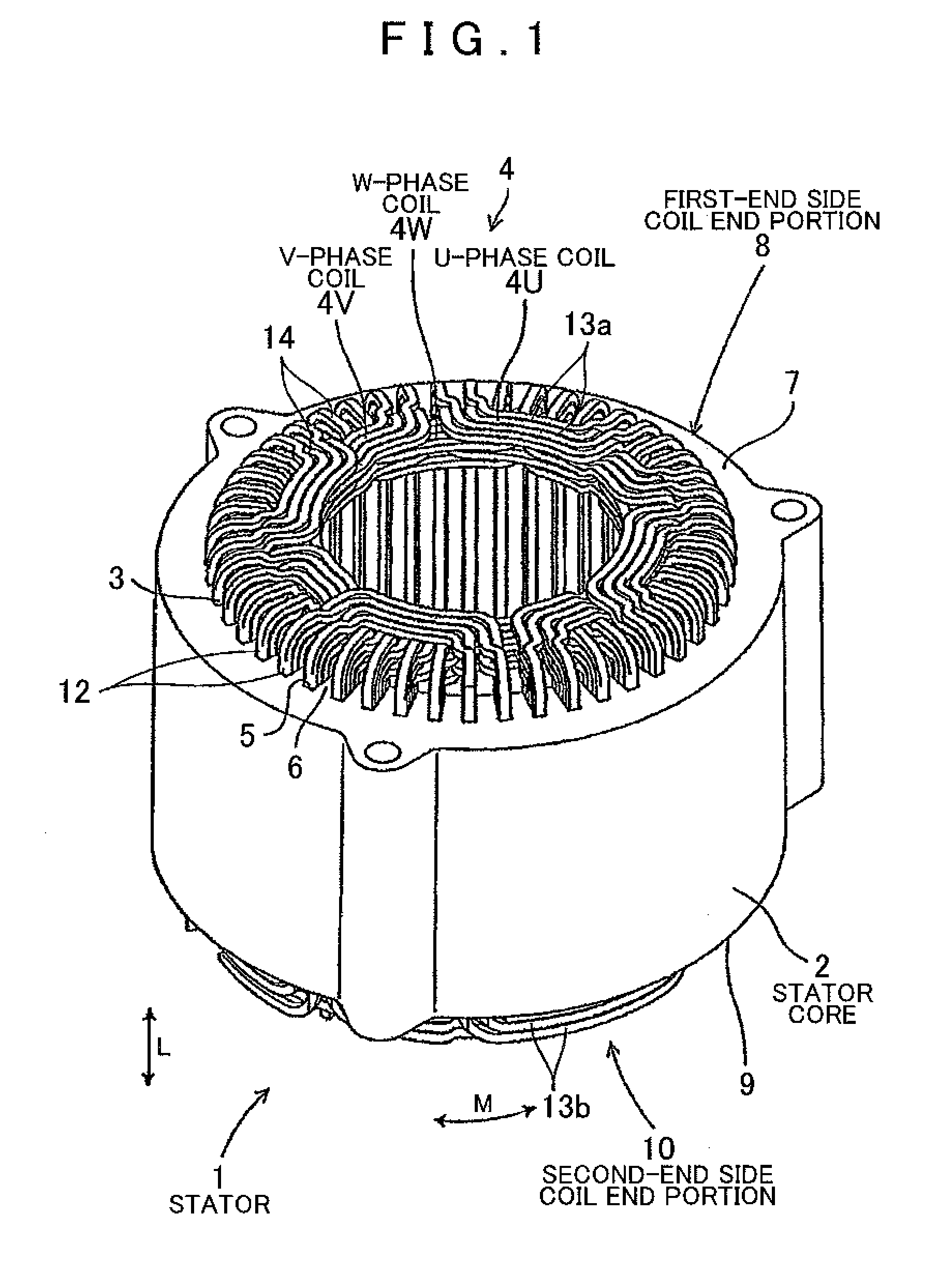
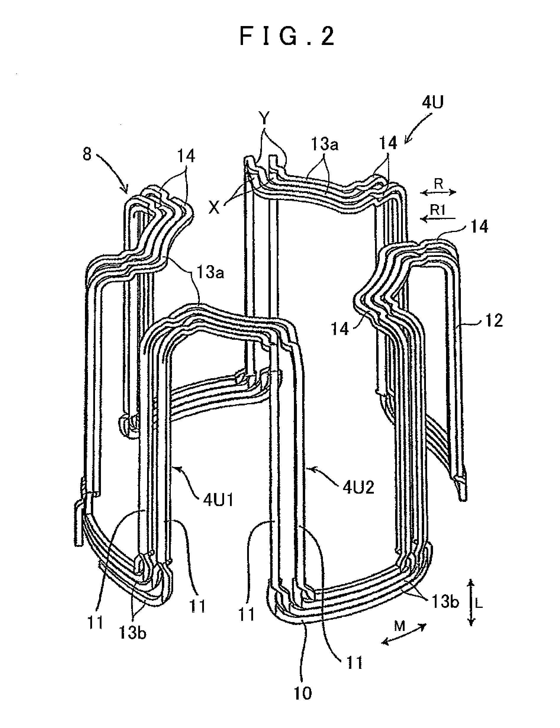
[0041]An embodiment of the present invention will be described with reference to the drawings. First, an example of a stator for a rotary electric machine (such as a motor and a generator) manufactured by a manufacturing apparatus and a manufacturing method for a stator according to the present invention will be described with reference to FIGS. 1 and 2. A stator 1 forms an electric motor (including a generator) together with a rotor. Such an electric motor is suitable as an electric motor (including a generator), in particular a brushless DC motor, serving as a drive source for electric vehicles and hybrid vehicles. As shown in FIG. 1, the stator 1 includes a stator core 2 formed by laminating a large number of thin silicon steel plates, and a coil 4 formed by winding a magnet wire (conductor, winding) 3 made of a predetermined material. The stator core 2 has a ring shape, opens radially inward and at both ends in the axial direction, and includes slots 5 and teeth 6 formed alterna...


PUM

PropertyMeasurementUnit
widthaaaaaaaaaa
circumferenceaaaaaaaaaa
specific poweraaaaaaaaaa

Abstract

An apparatus and a method for manufacturing a stator is disclosed. The stator includes a stator core having slots formed along an axial direction at a plurality of locations in a circumferential direction, and a coil formed by combining a plurality of rectangular wires that have a plurality of straight portions being disposed in the slots and arranged side by side in the circumferential direction and in a radial direction. A restriction jig having a number of restriction pieces is disposed on a first-end side of the coil in the axial direction. The coil is inserted into the stator core from the first-end side in the axial direction to dispose the straight portions in the slots. Circumferential positions of the straight portions are restricted along the axial direction through contact with the restriction pieces by relatively moving the restriction jig and the coil in the axial direction.

Description

INCORPORATION BY REFERENCE[0001]The disclosure of Japanese Patent Application No. 2009-251339 filed on Oct. 30, 2009 including the specification, drawings and abstract is incorporated herein by reference in its entirety.BACKGROUND OF THE INVENTION[0002]The present invention relates to a manufacturing method and a manufacturing apparatus for a stator for a rotary electric machine, for example, and more particularly to a manufacturing method and a manufacturing apparatus for a stator in which a coil formed by combining a plurality of rectangular wires with a rectangular cross section is disposed in a stator core by distributed winding.DESCRIPTION OF THE RELATED ART[0003]In general, rotary electric machines such as induction motors and direct-current motors (including generators) are widely used as power sources for industries or vehicles. Stator coils of the rotary electric machines are often formed by distributed winding which produces high specific power. It has recently been propos...

Claims


Application Information

Patent Timeline
Patent Type & Authority Applications(United States)
IPC IPC(8): H02K15/00
CPCH02K15/0435Y10T29/49009Y10T29/53143H02K15/067H02K15/0478
Inventor MISHINA, TOKUHISAHASHIMOTO, SHINGOSAITO, MASAKIIWATSUKI, KAZUYA
Owner AISIN AW CO LTD
Why Eureka
Try Eureka