Alignment fixture for x-ray images

a technology of alignment fixture and x-ray image, which is applied in the direction of radiation beam directing means, medical science, diagnostics, etc., can solve the problems of inability to physically locate the ruled grid at the same vertical plane as the patient's anatomical region, prior art devices and systems that require undue estimation, and the actual placement of the ruled grid in relation to the anatomical region of interest subject to an unacceptable margin of error, so as to achieve quick and easy x-

Active Publication Date: 2011-05-05
CARN RONALD M
View PDF23 Cites 38 Cited by
  • Summary
  • Abstract
  • Description
  • Claims
  • Application Information

AI Technical Summary

Benefits of technology

[0005]In accordance with the invention, an alignment fixture is provided for quickly and easily taking X-ray images of a patient, such as an X-ray image of the patient's pelvis and hip region preparatory to hip arthroplasty or hip replacement surgery. The alignment fixture comprises a frame having multiple support legs for resting on the patient at known positions, such as upon known bony prominences, in combination with a ruled grid on a grid plate which is adjustably positioned between an image beam source and the patient as a function of specific measured patient thickness, such as the thickness of the patient's pelvic region. The fixture supporting the ruled grid has at least two alignment sites for aligning the pelvis in the X-ray beam. As a result, the ruled grid overlies the anatomical region of interest to appear in an X-ray image with a known parallax image magnification corresponding with the parallax image magnification of a center of the anatomical region of interest, such as the patient's hip joint. X-ray images taken by use of the alignment fixture can be viewed and / or scaled for confidently selecting a properly sized prosthesis for the specific patient.
[0007]In one preferred form, the alignment fixture comprises a tripod frame having three legs depending from an upright frame post. The three frame legs are positioned for interactive patient retention on a respective trio of bony prominences on the patient, such as the anterior superior iliac spines and the symphysis pubis in the case of a hip replacement patient. The three tripod legs preferably include laterally or substantially horizontally turned feet for stable support respectively upon this trio of bony prominences, wherein the tripod feet may additionally include radio-opaque markers formed in an otherwise radio-transparent frame material (such as plastic) for assisting in placing the fixture frame onto patients of different typical sizes, such as a small-framed, medium-framed, or large-framed patient. These radio-opaque feet markers may appear in a resultant X-ray image to assist in confirming proper fixture alignment over the patient's skeletal structure.
[0009]Vertical adjustment of the grid plate is performed by first measuring the thickness of the selected anatomical region of the patient, such as the pelvic region in the case of a hip patient. From a knowledge of the relationship between patient thickness and a centerline through the anatomical region of interest, such as the hip joint, the grid plate is adjustably vertically positioned on the frame post in a manner so that the pair of ruled grids respectively overlie the anatomical region such as the patient's hip joints. In this regard, the radio-opaque feet markers assist in adjusting the position of the grid plate according to patient size. In addition, radio-opaque alignment marks such as fixture cross hairs formed on an upper alignment arm of the fixture frame and also on the grid plate spaced therebelow assist in aligning the patient and fixture relative to the X-ray beam source.
[0011]Accordingly, in one preferred form of the invention, the ruled grids each include radio-opaque grid lines or the like, with an actual known line-to-line distance less than a known as-marked measurement. In the preferred form, the marked measurement comprises a 1 centimeter (cm.) spacing, but the actual line spacing is less—about 0.6 cm. By appropriately adjusting the vertical position of the grid plate as a function of measured patient thickness, these spaced grid lines are projected onto the X-ray film or recording media in overlying relation to the selected anatomical region, such as the hip joints, with an parallax image magnification corresponding with the actual magnification of the anatomical region. By way of specific example, for an X-ray image having parallax magnification of the hip joints of about 125%, the grid lines will overlie the magnified image with an actual line spacing of about 1.25 cm. The resultant X-ray image can be scaled and viewed quickly and easily by a surgeon or the like for pre-surgery selection of a prosthesis of appropriate size for the particular patient.

Problems solved by technology

While this parallax magnification is not a problem in some X-ray imaging applications, such as diagnosis of a bone fracture or the like, it can be particularly problematic in an X-ray image taken prior to a surgical procedure involving implantation of a prosthesis, such as arthroplastic hip replacement surgery, wherein a primary reason for taking the pre-surgery X-ray image is to enable the surgeon to plan the surgery and to select a prosthesis of suitable size and design for the specific anatomy of the surgical patient.
However, the ruled grid cannot be physically located at the same vertical plane as the patient's anatomical region, particularly when that anatomical region comprises a structure such as a hip joint located deep within the patient.
For this reason, such prior art devices and systems have generally required undue estimation when used to indicate the size of a deep anatomical structure, such as a hip joint.
Accordingly, such prior art devices and systems have relied for accuracy largely upon the technique and skill of an individual X-ray technician, whereby the actual placement of the ruled grid in relation to the anatomical region of interest has been subject to an unacceptable margin of error.
As a result, confident pre-surgical prosthesis size determination based upon a pre-surgical X-ray image has remained an elusive objective.
Prior art does not address aligning the pelvis in the X-ray beam which is integral with consistent and accurate planning of the hip or pelvis surgery.

Method used


Image

  • Alignment fixture for x-ray images
  • Alignment fixture for x-ray images
  • Alignment fixture for x-ray images

Examples


Embodiment Construction

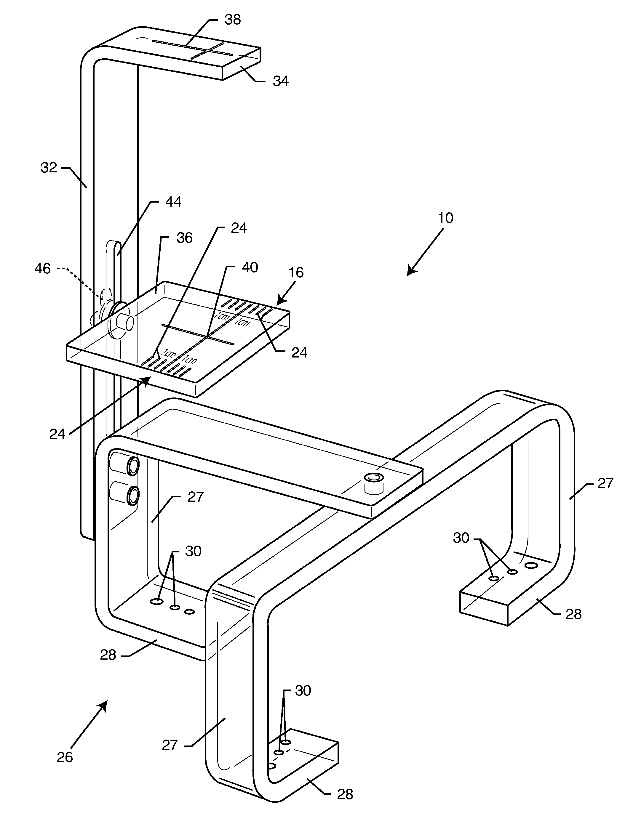
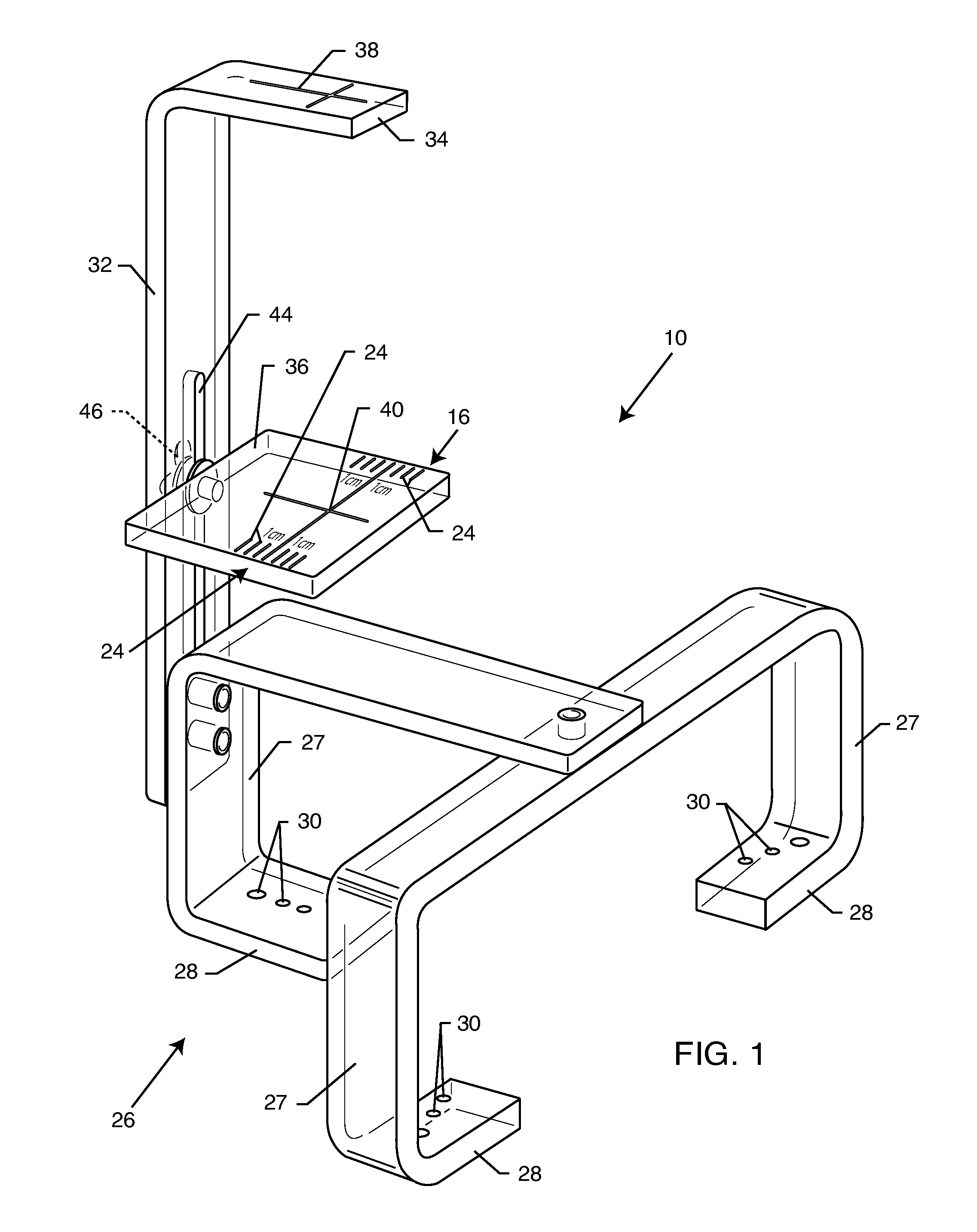
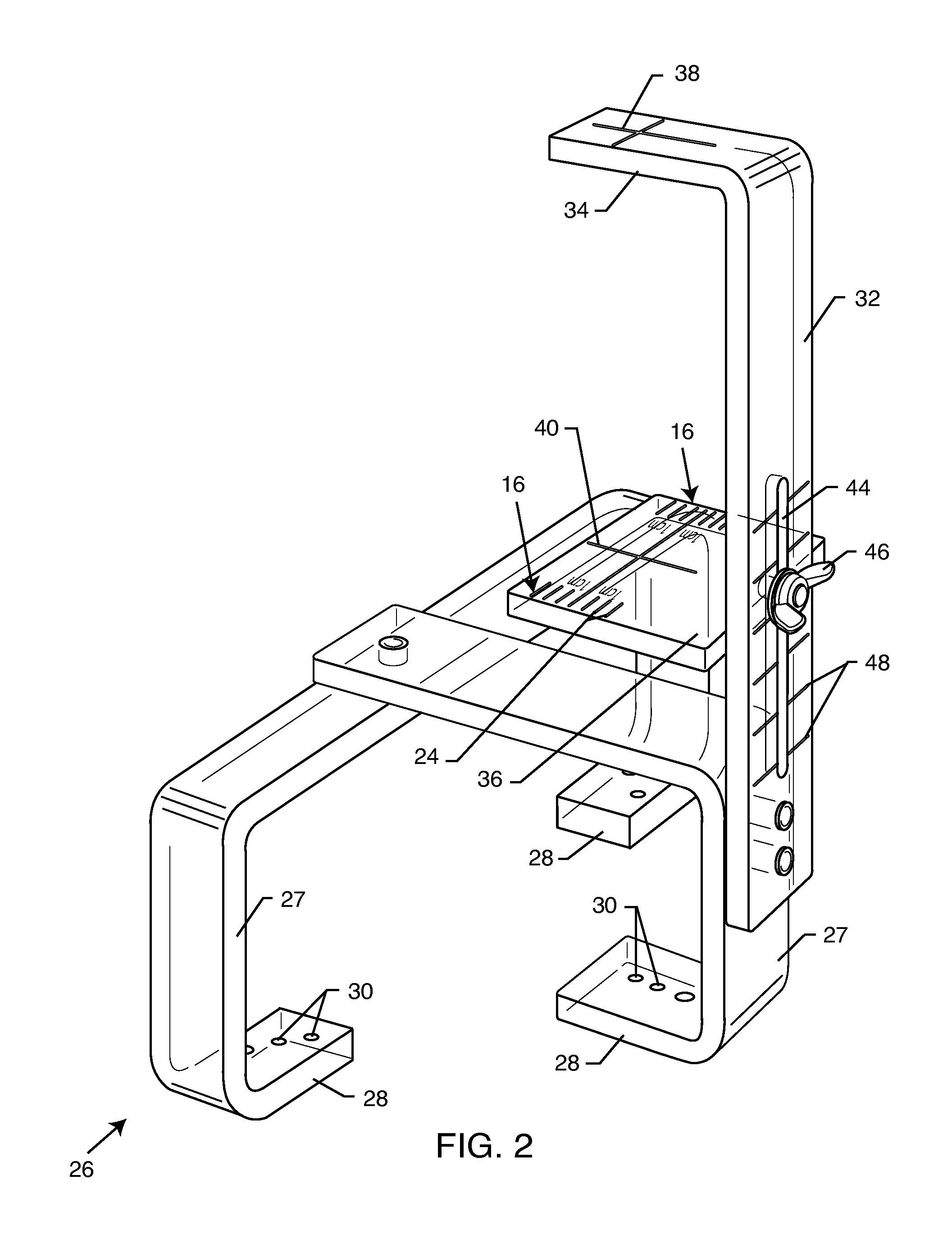
[0023]As shown in the exemplary drawings, an improved alignment fixture referred to generally by the reference numeral 10 in FIGS. 1-2 and 4-8 is provided for taking an X-ray image 12 (FIG. 9) of a patient 14 (FIGS. 3-6). The alignment fixture 10 is particularly designed for taking an X-ray image 12 preparatory to a prosthesis installation surgery (although FIG. 9 shows a pair of hip replacement prostheses 13 already installed), so that a prosthesis 13 of the correct size can be selected with confidence prior to the surgical procedure. In this regard, the alignment fixture 10 positions at least one radio-opaque ruled grid 16 at a selected vertical position above the patient 14, in accordance with the specific measured thickness (FIG. 4) of a selected anatomical region of the patient 14, such as the pelvic region in the case of a hip replacement patient. The vertical position of the ruled grid 16 is adjustably selected to overlay the selected anatomical region, such as a hip joint or...


PUM


Abstract

An alignment fixture for taking X-ray images of a patient, such as an image of the patient's hip region preparatory to hip arthroplasty. The alignment fixture comprises multiple support legs for resting on the patient at known positions, such as upon known bony prominences, in combination with aiming marks used for anatomically aligning the patent's pelvis under an X-ray beam. A ruled grid plate on the fixture is adjustably positioned between an image beam source and the patient, as a function of patient thickness in the pelvic region, so that a ruled grid overlays the anatomical region of interest and exhibits an apparent parallax image magnification corresponding with the parallax image magnification of a centerline of the anatomical region, such as the hip joint. X-ray images taken by use of the alignment fixture can be viewed and / or scaled to select a properly sized prosthesis for the specific patient.

Description

BACKGROUND OF THE INVENTION[0001]This invention relates generally to an improved alignment fixture and related method of use for taking X-ray images of a selected anatomical region of a patient, such as the pelvis and hip region preparatory to hip arthroplasty or hip replacement surgery, wherein the fixture aligns the pelvis in the X-ray beam and a ruled grid appears in the X-ray image to overlie the anatomical region of interest with a known parallax magnification corresponding with the parallax magnification of the anatomical region. Accordingly, X-ray images taken with the improved alignment fixture consistently align the pelvis and the projected grid and can be scaled quickly and easily for use in selecting a prosthesis size suitable for the specific patient.[0002]X-ray imaging is a known medical technique wherein X-rays are generated from a beam source to pass through a selected anatomical region of a patient. Some of the X-rays are absorbed by the patient whereas others pass t...

Claims


Application Information

Patent Timeline
Patent Type & Authority Applications(United States)
IPC IPC(8): A61B6/08
CPCA61B6/12A61B6/587A61B6/505
Inventor CARN, RONALD M.
Owner CARN RONALD M
Why Eureka
Try Eureka