Impending icing probe with thermal isolation pedestal

Active Publication Date: 2011-05-05
ROSEMOUNT AEROSPACE
View PDF18 Cites 5 Cited by
  • Summary
  • Abstract
  • Description
  • Claims
  • Application Information

AI Technical Summary

Problems solved by technology

The internal passageways are expensive to construct, difficult to inspect, and subject to plugging with debris during use, and difficult to clean.

Method used


Image

  • Impending icing probe with thermal isolation pedestal
  • Impending icing probe with thermal isolation pedestal
  • Impending icing probe with thermal isolation pedestal

Examples


embodiment 190

[0056]FIG. 15 illustrates a first probe embodiment 190 of the probe 100, shown in an oblique view. The probe 190 comprises a strut 140 that has a right circular cylinder cross section that is symmetrical and insensitive to angle of attack.

embodiment 192

[0057]FIG. 16 illustrates a second probe embodiment 192 of the probe 100, shown in an oblique view. The probe 190 comprises a strut 140 that has a swept, elongated aerodynamic cross section 180 that has a reduced aerodynamic drag. The strut 104 is shaped so as not to create airflow disturbances as the angle of attack varies during flight.

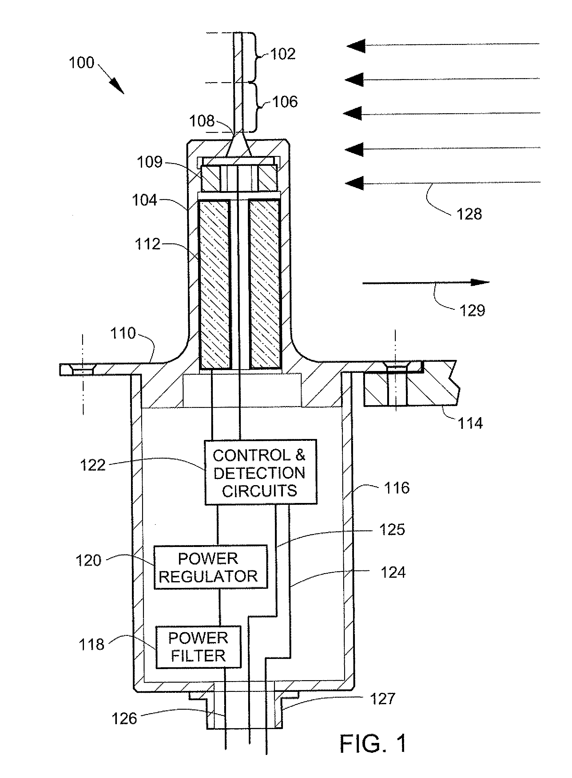
[0058]FIG. 17 illustrates an alternative thermal icing condition probe 101. The thermal icing condition probe 101 is similar to the thermal icing condition probe 100 in FIG. 1. Reference number used in FIG. 17 that are the same as reference numbers used in FIG. 1 identify the same or similar components in both FIGS. 1 and 17. In FIG. 17, an assembly of a detector 102 and a thermal isolation pedestal 106 extends through a central region surrounded by a strut heater 112 to an annular flange 155 that is inside an electronics housing 116. A seal 107 (such as epoxy environmental seal) seals an opening in a strut 104. A seal 111 (such as a metal-to-metal ...


PUM


Abstract

In an icing condition detection system, a circuit provides an output representing impending icing conditions as a function of power consumption of a single element detector. A thermal isolation pedestal includes a detector support end that supports the single element detector and an opposite strut mounting end. A thermal isolation controller controls a thermal isolation pedestal temperature to thermally isolate the single element detector from a strut mounting end.

Description

FIELD OF THE INVENTION[0001]The present invention relates generally to thermal icing condition detection on aircraft.BACKGROUND OF THE INVENTION[0002]Various types of thermal icing condition detectors for aircraft are known. Thermal icing condition detectors typically include a “wet” thermal sensor that is exposed to atmospheric conditions including water and ice, and a “dry” thermal sensor that is shielded from icing. The shielding from icing typically uses complex internal probe passageways to separate water and ice from the “dry” thermal sensor. The internal passageways are expensive to construct, difficult to inspect, and subject to plugging with debris during use, and difficult to clean.[0003]Embodiments of the present invention provide solutions to these and other problems, and offer other advantages over the prior art.SUMMARY OF THE INVENTION[0004]Disclosed is an icing condition detection system. The icing condition detection system comprises a single element detector. The ic...

Claims


Application Information

Patent Timeline
IPC IPC(8): G05D23/19
CPCB64D15/20
Inventor HEUER, WESTON D.C.KANE, BRIANWILLCOX, CHARLES
Owner ROSEMOUNT AEROSPACE
Why Eureka
Try Eureka