
Pressure control valve driving circuit for pressure type flow rate control device with flow rate self-diagnosis function

a technology of flow rate control and pressure control valve, which is applied in the direction of valve operating means/release devices, process and machine control, instruments, etc., can solve the problems of greater influence and difficulty in precisely measuring pressure drop characteristics, and achieve high accuracy and stably performing measurement of pressure drop characteristics. , the effect of rapid switching of the pressure control valv

Active Publication Date: 2011-05-12
FUJIKIN INC
View PDF5 Cites 8 Cited by
  • Summary
  • Abstract
  • Description
  • Claims
  • Application Information

AI Technical Summary

Benefits of technology

[0028]In accordance with the present invention, in the pressure control valve driving circuit for the pressure type flow rate control device, which is provided with the flow rate self-diagnosis function, a closing circuit for closing a control valve at a high speed is provided in parallel with a control valve driving circuit. Therefore, it is possible to rapidly switch the pressure control valve from being fully opened to being completely closed in a manner that considerably shortens the valve closing time delay of the pressure control valve. In accordance with these features of the invention, it is possible to highly accurately and stably perform measurement of pressure drop characteristics in a flow rate self-diagnostic, which leads to a highly accurate diagnosis result of the flow rate self-diagnostic.

Problems solved by technology

In addition, a time position at the first sampling point in measurement of the pressure drop characteristics (i.e., sampling start time) fluctuates, which makes it difficult to precisely measure the pressure drop characteristics.
Furthermore, the shorter the sampling time for a diagnostic, the greater is the influence on the pressure drop characteristics caused by the delay in dropping of the piezoelectric element driving voltage.

Method used


Image

  • Pressure control valve driving circuit for pressure type flow rate control device with flow rate self-diagnosis function
  • Pressure control valve driving circuit for pressure type flow rate control device with flow rate self-diagnosis function
  • Pressure control valve driving circuit for pressure type flow rate control device with flow rate self-diagnosis function

Examples


Embodiment Construction

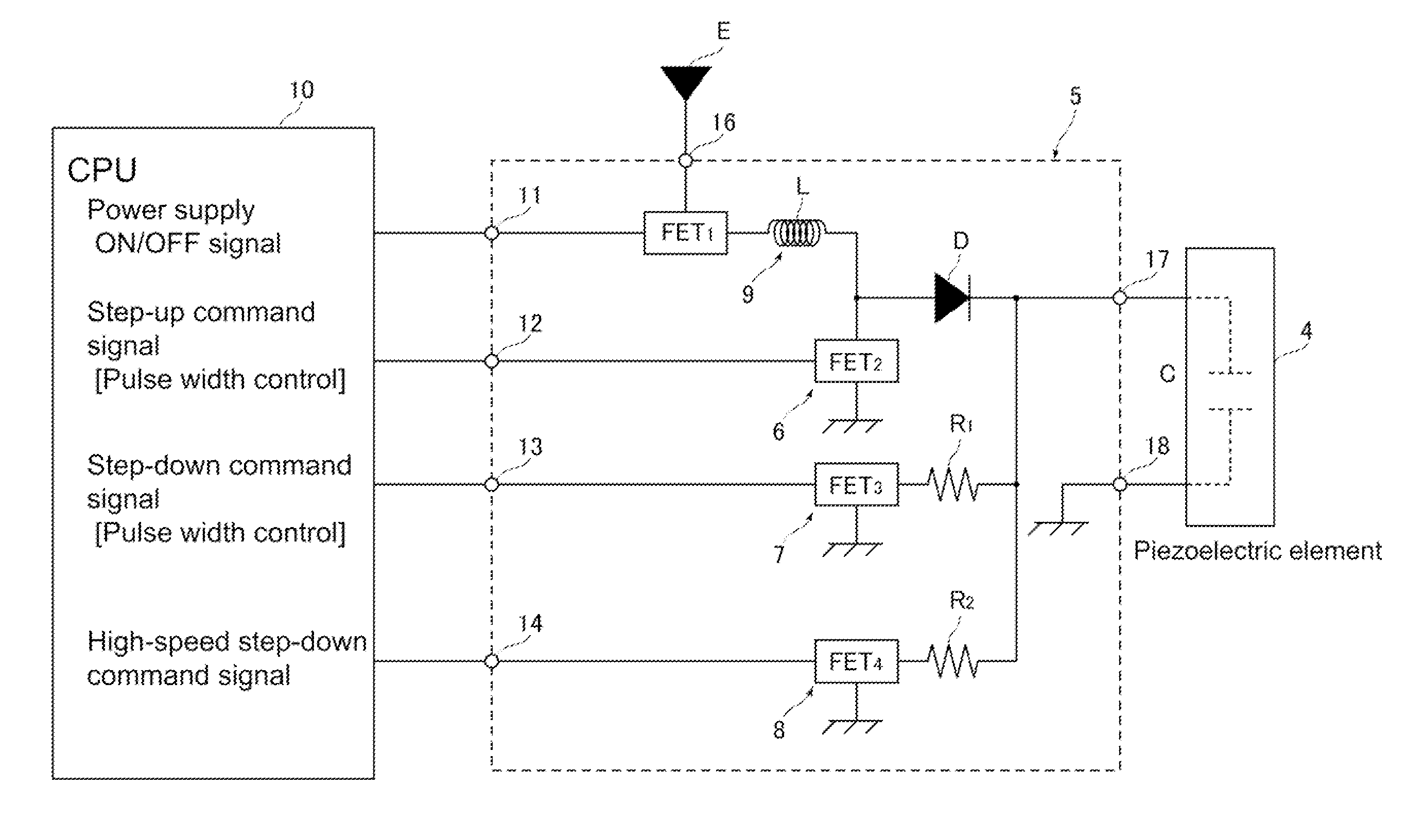
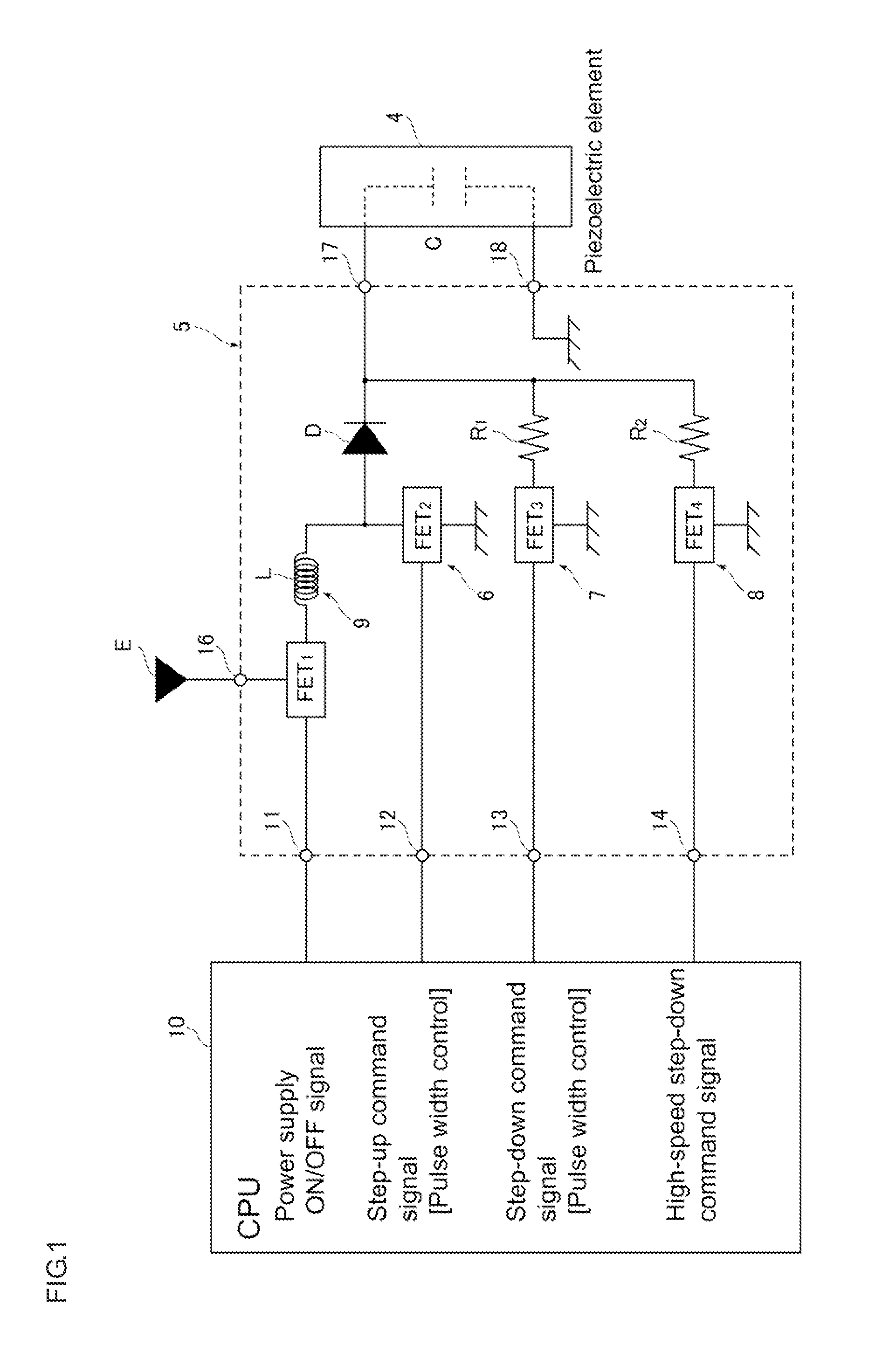
[0039]Hereinafter, an embodiment of the present invention will be described with reference to the accompanying drawings, wherein like parts are designated by like character references. FIG. 1 is a block diagram showing the circuit configuration of a piezoelectric element driving circuit for a pressure type flow rate control device that is provided with a flow rate self-diagnosis function according to the present invention. In FIG. 1, reference numeral 4 denotes a piezoelectric element, reference numeral 5 denotes a piezoelectric element driving circuit, reference numeral 6 denotes a step-up command circuit, reference numeral 7 denotes a step-down command circuit, reference numeral 8 denotes a high-speed step-down command circuit, reference numeral 9 denotes a step-up voltage supply circuit, and reference numeral 10 denotes an arithmetic device (CPU) of the pressure type flow rate control device. Furthermore, reference character E is a power supply, reference numerals 11, 12, 13, 14 ...


PUM


Abstract

A pressure control valve piezoelectric element driving circuit is provided for a pressure type flow rate control device provided with a flow rate self-diagnosis function for comparing initial pressure drop characteristics data measured and with pressure drop characteristics data in a flow rate diagnosis which are measured under conditions that are the same for both measurements to detect malfunction in flow rate control from a difference between both characteristics data, wherein a first discharge circuit slowly discharges a piezoelectric element driving voltage applied to the piezoelectric element according to a step-down command signal from a CPU, through a step-down command circuit to step down the voltage, and a second discharge circuit that rapidly discharges a piezoelectric element driving voltage applied to the piezoelectric element according to a high-speed step-down command signal from the CPU, through a high-speed step-down command circuit to step down the voltage.

Description

[0001]This is a National Phase Application in the United States of International Patent Application No. PCT / JP2009 / 000647 filed Feb. 18, 2009, which claims priority on Japanese Patent Application No. 2008-115479, filed Apr. 25, 2008. The entire disclosures of the above patent applications are hereby incorporated by reference.BACKGROUND OF THE INVENTION[0002]1. Technical Field of the Invention[0003]The present invention relates to improvements in a pressure type flow rate control device for gas, or the like, used for manufacturing semiconductors, chemicals, drugs, precision machinery components, or the like. The present invention relates to a pressure control valve driving circuit that is capable of constantly performing highly accurate and stable detection at the time of detecting a change in shape of an orifice due to clogging, cracks, corrosion, or the like, by use of a flow rate self-diagnosis function provided for the pressure type flow rate control device.[0004]2. Background Ar...

Claims


Application Information

Patent Timeline
Patent Type & Authority Applications(United States)
IPC IPC(8): F16K31/12
CPCG05D7/0635Y10T137/7762
Inventor SUGITA, KATSUYUKIIKEDA, NOBUKAZUNISHINO, KOUJIDOHI, RYOUSUKEHIRATA, KAORUNAKATANI, TAKATOSHI
Owner FUJIKIN INC
Learn More