

Pivoted visor assembly
a visor and assembly technology, applied in the field of vehicle visors, can solve the problems of momentarily distracted operators, difficult to manipulate the visors without distracting the vehicle operator, etc., and achieve the effect of improving the protection of the side windows
- Summary
- Abstract
- Description
- Claims
- Application Information
AI Technical Summary
Benefits of technology
Problems solved by technology
Method used
Image

Examples
Embodiment Construction
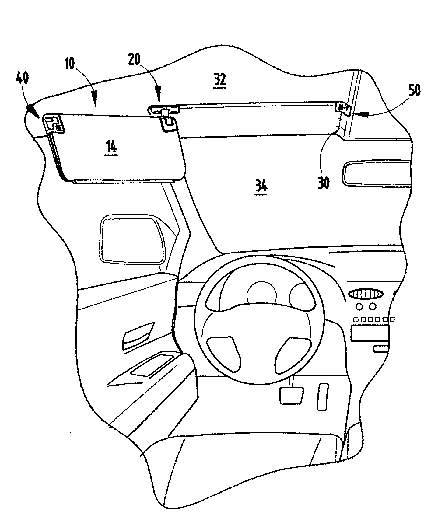
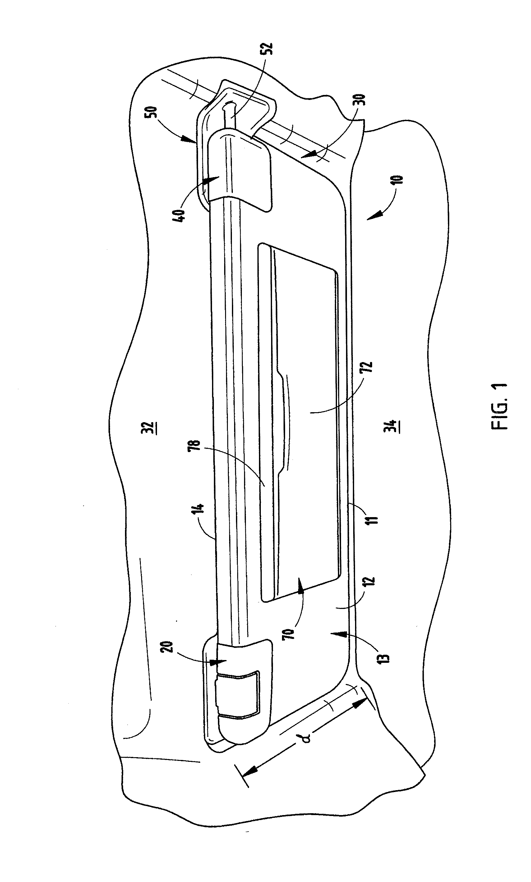
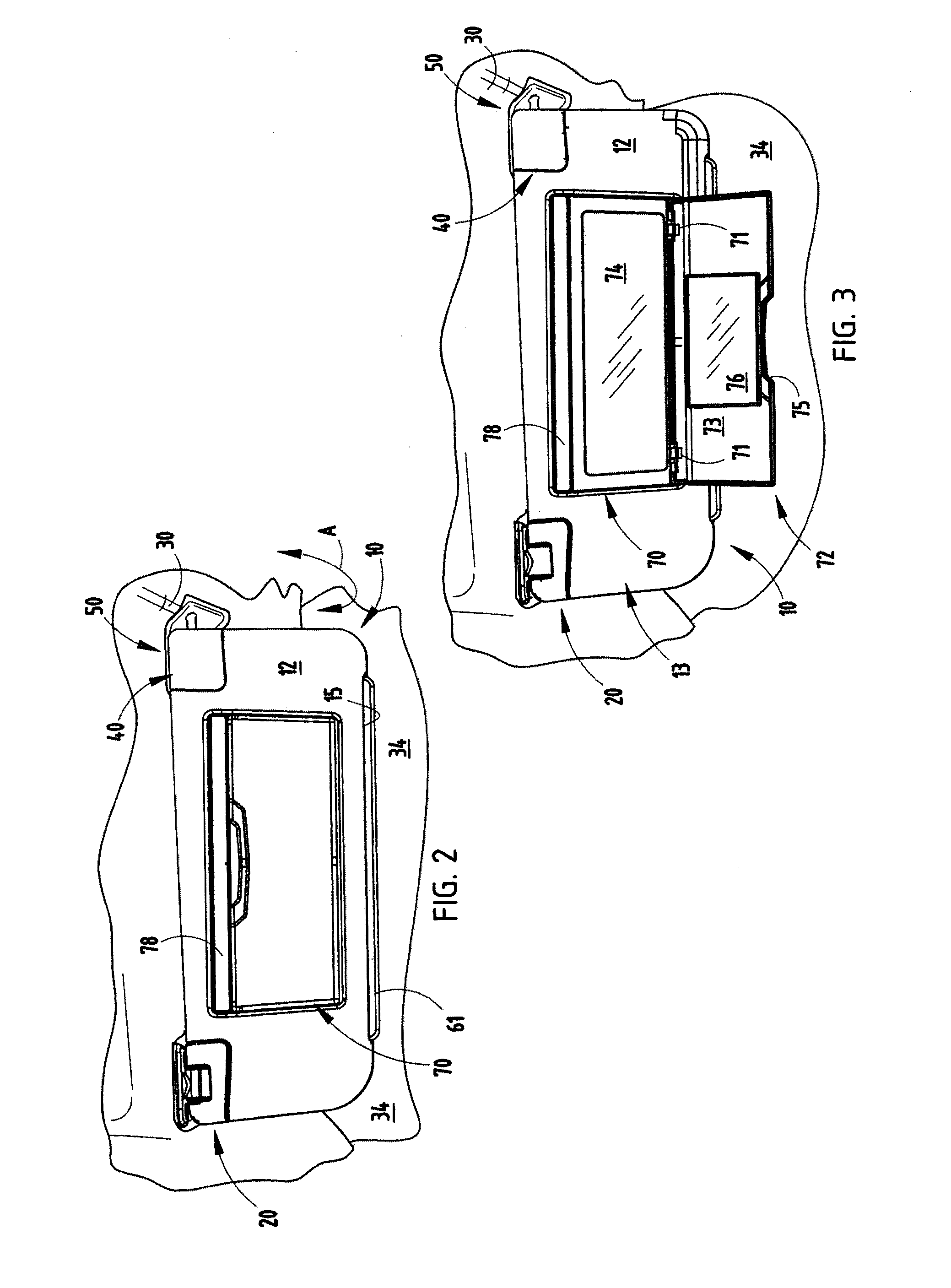
[0046]Referring initially to FIG. 1, there is shown a visor assembly 10 of the present invention which includes a pivot mounting assembly 20, which mounts the visor assembly 10 within a forward pocket 30 of a vehicle headliner 32 immediately adjacent the vehicle's windshield 34. The pivot assembly 20 is positioned rearwardly of the windshield 34 and attached to the headliner 32 or underlying sheet metal structure of the vehicle roof. It is spaced a distance “d”, in one embodiment, of approximately 6½ inches, such that the forward edge 11 of the visor assembly 10 is immediately adjacent the vehicle windshield 34. This distance will vary depending upon the height of the body of visor 10. Visor assembly 10 also includes a mounting bracket assembly 40 at an end of the visor 10 opposite pivot mounting assembly 20, which holds the right edge of the visor (as viewed in FIG. 1) in a stored position as described below and shown in FIG. 1 but releasably allows the visor to pivot downwardly an...
PUM
 Abstract
Description
Claims
Application Information