
Visor with pivoted side window panel

Inactive Publication Date: 2013-02-07
MARCUS AUTOMOTIVE
View PDF4 Cites 5 Cited by
  • Summary
  • Abstract
  • Description
  • Claims
  • Application Information

AI Technical Summary

Benefits of technology

The invention is a visor system for vehicles that includes a primary visor and an auxiliary visor. The primary visor is mounted on the vehicle headliner and can pivot downward to block sun from entering through the side window. The auxiliary visor can pivot upward and to the side to block sun from entering through the side window. The system also includes a sun-blocking glare shield that can be extended or retracted as needed. The unique mounting arrangement of the visors prevents any potential danger in case of an accidental bump. The system also includes optional features like illuminated vanity mirrors and extendable sun-blocking panels. Overall, the invention provides improved side window protection and other desirable features for vehicles.

Problems solved by technology

With such conventional mounting systems for vehicle visors, at least two safety issues are presented.
First, the operator is momentarily distracted while manipulating the visor for use either in the front windshield position, since it passes through the line of sight, and again when it is pivoted to a side window position.
Secondly, when pivoted downwardly, the visor may in some adjusted positions present an edge which projects toward the user's head.
In the event of an accident, this could cause serious injury despite requirements that the edges of the visor have curved edges.
Newer vehicle designs have become more aerodynamic, partly to conserve fuel, and, in such designs, conventional visor mounting systems place the visors further rearwardly even closer to the occupant's head, which makes it more difficult to manipulate the visor without distracting, particularly, the vehicle operator.
Movement of such auxiliary visors likewise is through the driver's head zone and can cause a significant distraction while operating a motor vehicle.

Method used


Image

  • Visor with pivoted side window panel
  • Visor with pivoted side window panel
  • Visor with pivoted side window panel

Examples


Embodiment Construction

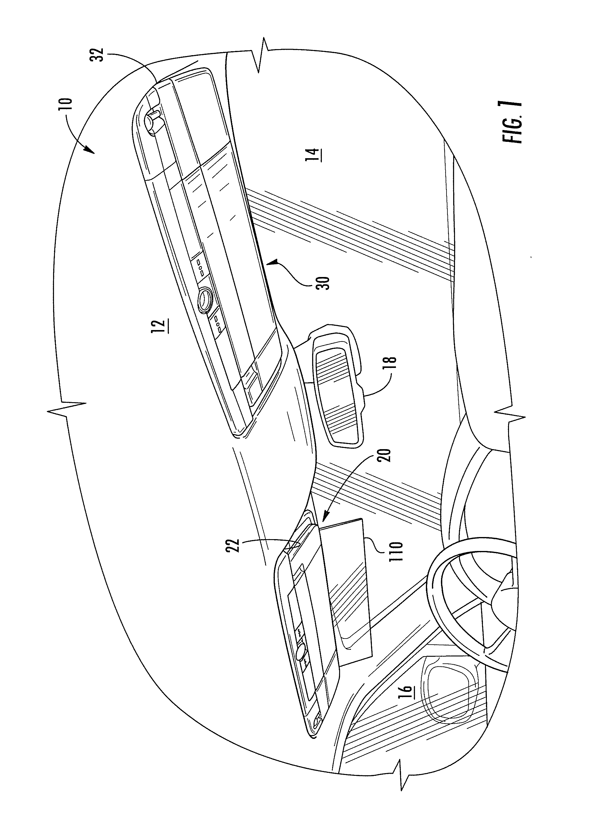
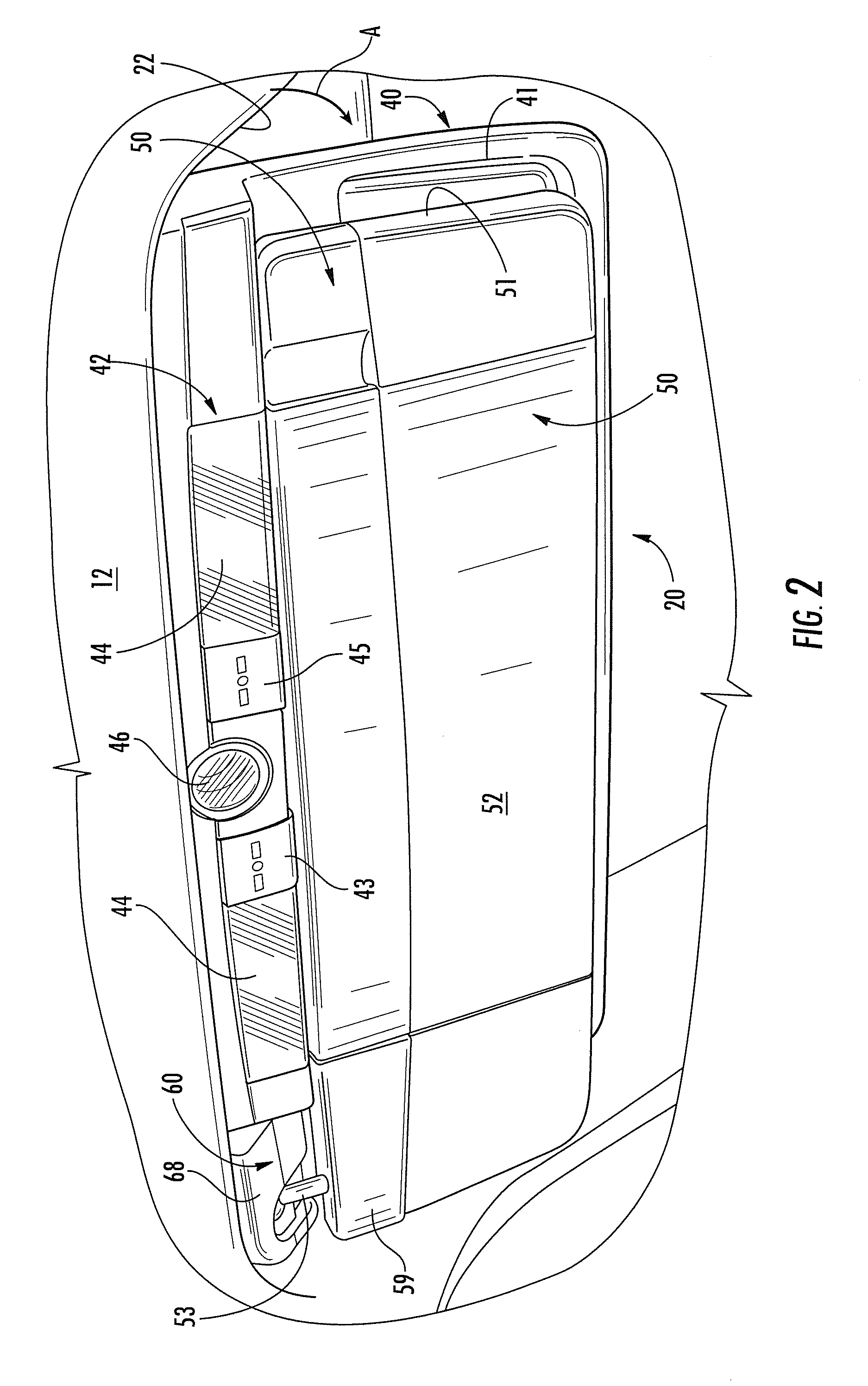
[0035]Referring initially to FIG. 1, there is shown a vehicle 10, such as an automobile, having a headliner 12, windshield 14, side window 16, rearview mirror assembly 18 extending from the headliner 12, and a pair of visor assemblies including a driver's side visor assembly 20 and a passenger side visor assembly 30, both of which embody the present invention. The visor assemblies 20 and 30 are mounted in recessed pockets 22 and 32 of the headliner 12 to be nestably received therein when in a stored position, as shown in FIG. 1. The visors pivot downwardly and away from the windshield, as illustrated by arrow A in FIG. 2, for the visor assembly 20.

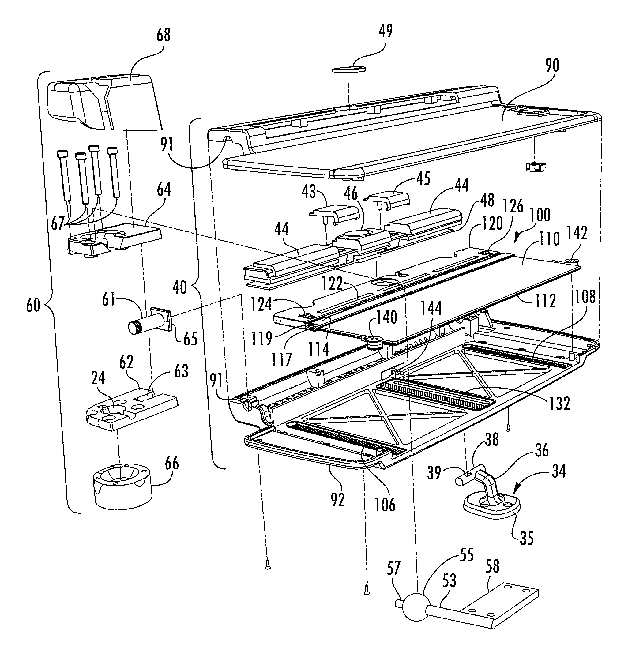
[0036]Visor assemblies 20 and 30 are substantially identical with mirror image mounting brackets and a detailed description of visor assembly 20 is presented, it being understood that assembly 30 is substantially the same with the mounting system reversed for use as a passenger side visor. Before discussing the visor construction in detail...


PUM


Abstract

A visor system is mounted to a vehicle such that it pivots from a pocket in a vehicle headliner adjacent the windshield downwardly away from the windshield from a stored position to a use position. The system includes a primary visor which remains in the front windshield position and an auxiliary visor panel pivotally mounted to the vehicle for pivoting downwardly and then upwardly to a side window position without encroaching in a user's space. The primary visor includes a pivoted extendable glare shield which can be deployed from an edge of the primary visor to increase sun blocking or filtering.

Description

CROSS-REFERENCE TO RELATED APPLICATIONS[0001]This application claims priority under 35 U.S.C. §119(e) and the benefit of U.S. Provisional Application Nos. 61 / 326,721 entitled VISOR WITH PIVOTED SIDE WINDOW PANEL, filed on Apr. 22, 2010, by Konrad H. Marcus, et al. and 61 / 360,706 entitled AUXILIARY GLARE SHIELD MODULE, filed on Jul. 1, 2010, by Konrad H. Marcus, et al., the entire disclosures of which are incorporated herein by reference.BACKGROUND OF THE INVENTION[0002]The present invention relates to vehicle visors and particularly to a visor assembly having a unique pivoted auxiliary visor and mounting structure for attaching the visor to a vehicle.[0003]Typically visors are mounted to a vehicle with a pivot hinge arrangement coupled to the vehicle roof near or at the A-pillar of the vehicle. When used, such visors are pivoted downwardly in a direction toward the windshield passing momentarily through the forward line of sight of the occupant as it is moved to a sun-blocking posit...

Claims


Application Information

Patent Timeline
IPC IPC(8): B60J3/02B60J1/20
CPCB60J3/0208B60J3/0278B60J3/0273B60J3/0226
Inventor MARCUS, KONRAD H.FLUHARTY, WILLIAM J.HOGG, CHRISTOPHER L.
Owner MARCUS AUTOMOTIVE
Learn More