Visor with movable pivot

a technology of visors and pivots, applied in the field of vehicle visors, can solve the problems of momentarily distracted operators, serious injuries, and difficulty in manipulating the visors without distracting, and achieve the effect of selecting the amount of sun protection

Inactive Publication Date: 2014-05-06
DEWITT SUCCESSOR TRUSTEE OF THE JACK L DEWITT TRUST UAD OCTOBER 10 1980 AS AMENDED JAMES R +1
View PDF23 Cites 2 Cited by
  • Summary
  • Abstract
  • Description
  • Claims
  • Application Information

AI Technical Summary

Benefits of technology

[0007]According to one embodiment of the invention, a visor is provided which pivots downwardly away from the windshield and includes a movable pivot axis that moves the visor toward the vehicle windshield and away from the operator as the operator lowers the visor. This moves the visor to a comfortable and functional position for the operator. In one embodiment, the visor also includes an extendable and retractable sun-blocking or screening glare shield. The glare shield is pivotally adjusted with respect to the primary visor and can be deployed when the primary visor is in a raised stored position or a lowered use position to provide a selectable amount of sun-blocking protection.
[0008]In another preferred embodiment of the invention, the visor includes an illuminated vanity mirror having lights to serve as a map lamp, courtesy lamp, and / or facial illuminating light source. In yet another preferred embodiment of the invention, the visor includes a covered mirror and the inside of the cover includes a magnifying mirror for assisting the user in detailed facial makeup.

Problems solved by technology

With such conventional mounting systems for vehicle visors, at least two safety issues are presented.
First, the operator is momentarily distracted while manipulating the visor for use either in the front windshield position, since it passes through the line of sight, and again when it is pivoted to a side window position.
Secondly, when pivoted downwardly, the visor may in some adjusted positions present an edge which projects toward the user's head.
In the event of an accident, this could cause serious injury despite requirements that the edges of the visor are curved.
Newer vehicle designs have become more aerodynamic, partly to conserve fuel, and, in such designs, conventional visor mounting systems place the visors further rearwardly even closer to the occupant's head, which makes it more difficult to manipulate the visor without distracting, particularly, the vehicle operator.
Movement of such auxiliary visors likewise is through the driver's head zone and can cause a significant distraction while operating a motor vehicle.

Method used


Image

  • Visor with movable pivot
  • Visor with movable pivot
  • Visor with movable pivot

Examples


Embodiment Construction

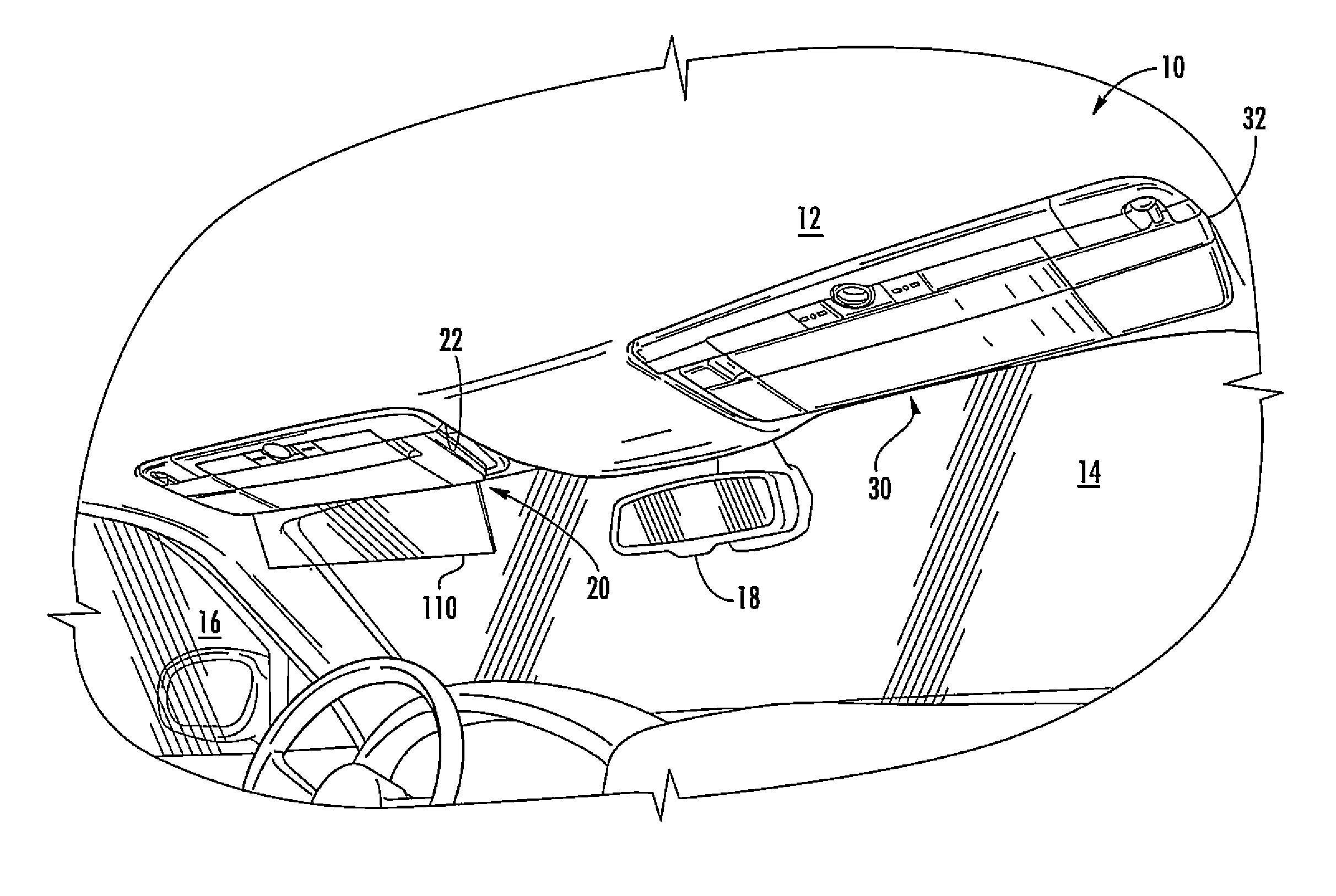
[0016]Referring initially to FIG. 1, there is shown a vehicle 10, such as an automobile, having a headliner 12, windshield 14, side window 16, and rearview mirror assembly 18. A pair of visor assemblies include a driver's side visor 20 and a passenger side visor 30, both of which embody the present invention. The visors 20 and 30 are mounted in recessed pockets 22 and 32 of the headliner 12 to be nestably received therein when in a stored position, as shown in FIG. 1. The visors pivot downwardly and away from the windshield.

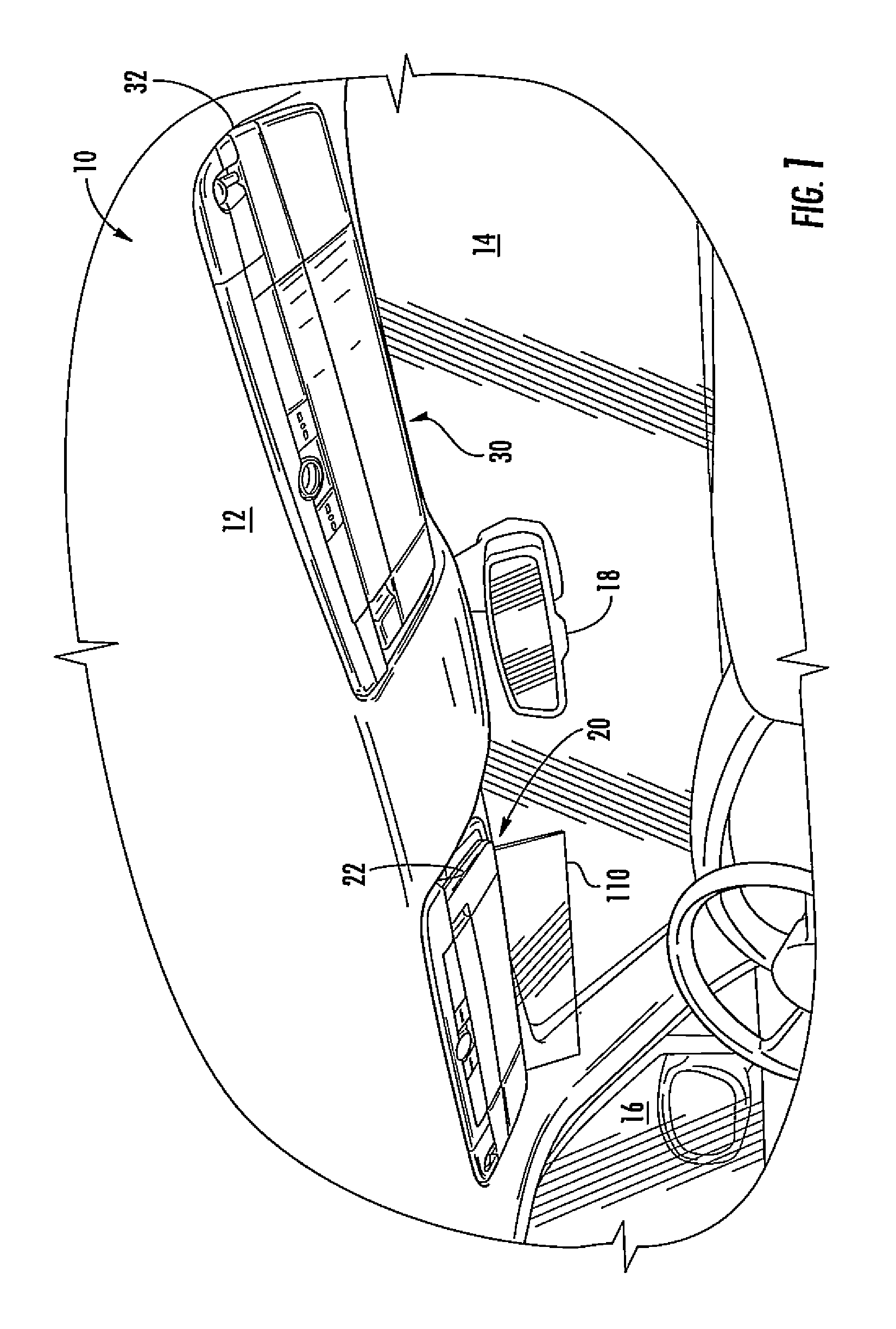
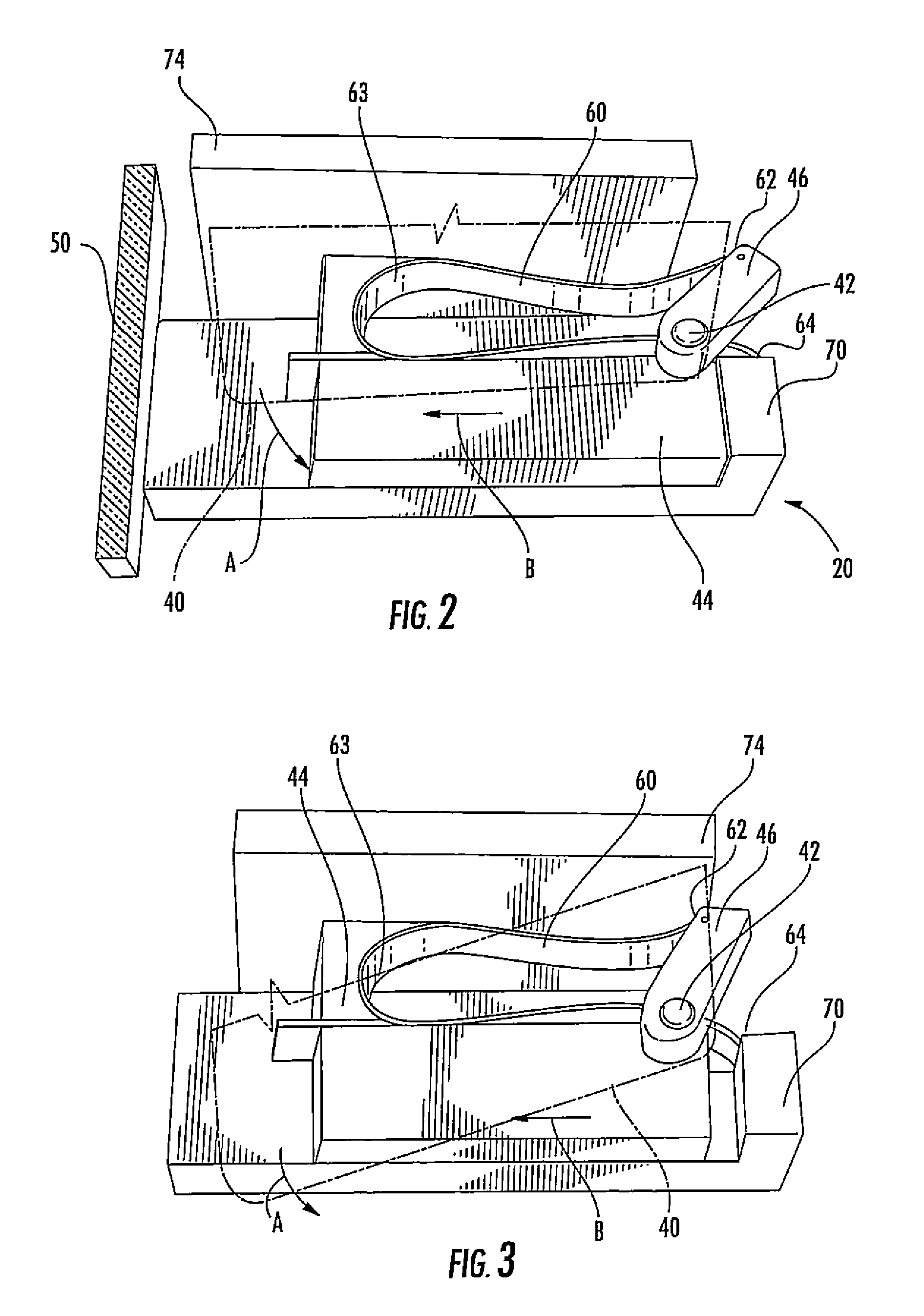
[0017]Visors 20 and 30 are substantially identical with mirror image mounting brackets. The visors themselves are disclosed in greater detail in WO 2011 / 133791, published Oct. 27, 2011, the disclosure of which is incorporated herein by reference with respect to the visors themselves. The unique mounting of the visors to the roof 12 of the vehicle is described in conjunction with FIGS. 2-5 of this application. The visors 20, 30 may include a rotatable glare shield...


PUM


Abstract

A visor is provided which pivots downwardly away from the windshield and includes a movable pivot axis that moves the visor toward the vehicle windshield and away from the operator as the operator lowers the visor. This moves the visor to a comfortable and functional position for the operator.

Description

CROSS-REFERENCE TO RELATED APPLICATIONS[0001]This application claims priority under 35 U.S.C. §119(e) and the benefit of U.S. Provisional Application No. 61 / 578,328 entitled VISOR WITH MOVABLE PIVOT, filed on Dec. 21, 2011, by Konrad H. Marcus, et al., the entire disclosure of which is incorporated herein by reference.BACKGROUND OF THE INVENTION[0002]The present invention relates to vehicle visors and particularly to a visor assembly having a unique movable pivot mounting structure for attaching the visor to a vehicle.[0003]Typically visors are mounted to a vehicle with a pivot hinge arrangement coupled to the vehicle roof near or at the A-pillar of the vehicle. When used, such visors are pivoted downwardly in a direction toward the windshield passing momentarily through the forward line of sight of the occupant as it is moved to a sun-blocking position. Also, conventional visor mounts frequently employ an auxiliary releasing clip at an end opposite the pivot connection to allow the...

Claims


Application Information

Patent Timeline
Patent Type & Authority Patents(United States)
IPC IPC(8): B60J3/02
CPCB60J3/0239B60J3/0213
Inventor MARCUS, KONRAD H.BOEREMA, EDWARD T.
Owner DEWITT SUCCESSOR TRUSTEE OF THE JACK L DEWITT TRUST UAD OCTOBER 10 1980 AS AMENDED JAMES R
Why Eureka
Try Eureka