System and method for controlling fuel supplied to an engine

Active Publication Date: 2018-03-01
FORD GLOBAL TECH LLC
View PDF11 Cites 2 Cited by
  • Summary
  • Abstract
  • Description
  • Claims
  • Application Information

AI Technical Summary

Benefits of technology

[0007]The present description may provide several advantages. In particular, the approach may provide improved fuel injection control by permitting higher gains so that fuel injection errors may be reduced in a more timely manner. Further, the approach p

Problems solved by technology

The fueling differences may result from engine component tolerance variation, sensor measurement errors, and errors in open loop fuel control parameters.
If the value of the gain is small, a long period of time may be needed to drive the engine air-fuel ratio error toward a value of zero.
However, if the gain is made too large, the engine air-fuel ratio may be driven to oscillate about the desired engine air-fuel ratio.
The oscillations may increase engine emissions and degrade vehicle drivability.
The delay may also include the amount of time it takes the engine to rotate through the exhaust stroke of the cylinder receiving the fuel and release exhaust gases from the cylinder into the exhaust

Method used


Image

  • System and method for controlling fuel supplied to an engine
  • System and method for controlling fuel supplied to an engine
  • System and method for controlling fuel supplied to an engine

Examples


Embodiment Construction

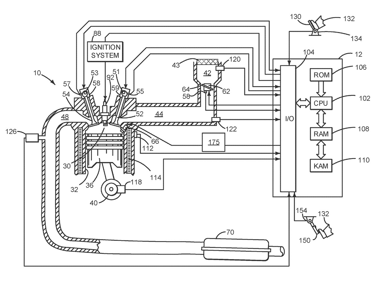
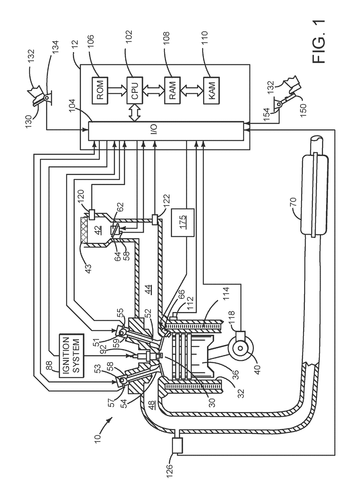
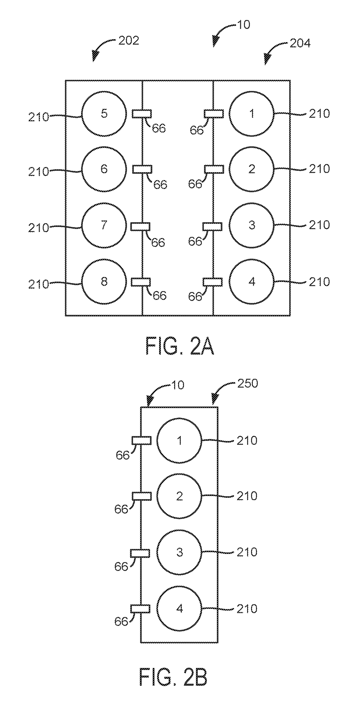
[0018]The present description is related to determining fuel injection delay for an engine that includes cylinders that may be deactivated and reactivated from time to time. The fuel injection delay determining methods described herein may be applied to a cylinder bank of an engine. Fuel injection delay times of multiple cylinder bank engines may be determined via reproducing the methods for determining fuel injection timing for a single bank of cylinders and applying the method to other cylinder banks. An engine cylinder of an engine is shown in FIG. 1. The engine cylinder of FIG. 1 may be part of an engine that includes multiple cylinders as shown in FIGS. 2A and 2B. Fuel supplied to a bank of cylinders may be regulated via a controller as shown in FIG. 3. FIGS. 4-6 show methods for determining fuel injection delay. FIGS. 7 and 8 show example sequences where fuel injection delay is determined.

[0019]Referring to FIG. 1, internal combustion engine 10, comprising a plurality of cylin...


PUM


Abstract

Systems and methods for determining fuel delay in a fuel injected engine with cylinders that may be deactivated are presented. In one example, the fuel injection delay is determined via a cylinder firing schedule array when the cylinder firing schedule array is available. The fuel injection delay is determined via weighted average of a fuel injection delay of a present engine cycle and a fuel injection delay of a past engine cycle when the cylinder firing schedule array is not available.

Description

FIELD[0001]The present description relates to a system and methods for supplying fuel to a variable displacement engine. The system and methods provide for adjusting a fuel delay compensation value responsive to whether or not fuel is delivered to engine cylinders.BACKGROUND AND SUMMARY[0002]Fuel may be injected to an internal combustion engine so that the engine may provide a requested or desired torque. The amount of fuel injected to the engine may be different than an amount of fuel commanded to be injected to the engine. Further, the amount of fuel requested to be injected may be different than an amount of fuel that provides a desired engine air-fuel mixture ratio. The fueling differences may result from engine component tolerance variation, sensor measurement errors, and errors in open loop fuel control parameters. An estimate of engine air-fuel ratio may be determined via an oxygen sensor, and the engine air-fuel ratio may be fed back to an engine controller to compensate err...

Claims


Application Information

Patent Timeline
IPC IPC(8): F02D41/14F02D41/00F02D41/30
CPCF02D41/1481F02D41/3005F02D41/0087F02D41/1479F02D35/02F02D41/008F02D41/047F02D41/1401F02D41/401F02D2041/1409F02D41/1482F02D41/1483F02D41/2451F02D41/40F02D2041/1412F02D2041/1431F02D2041/389Y02T10/40F02D2200/0618F02D2041/2055
Inventor MAGNER, STEPHEN WILLIAMJANKOVIC, MRDJAN J.
Owner FORD GLOBAL TECH LLC
Why Eureka
Try Eureka