
System for tensioning a surgical wire

a surgical wire and tensioning technology, applied in the field of surgical wire tensioning systems, can solve the problems of wire digging into and damage bone on one side, inadequate tensioning of wire tensioners for surgical use, and lack of equalizing mechanism of tension applied to the two ends of the tensioner,

Active Publication Date: 2011-05-12
ACUTE INNOVATIONS
View PDF47 Cites 188 Cited by
  • Summary
  • Abstract
  • Description
  • Claims
  • Application Information

AI Technical Summary

Problems solved by technology

Wire tensioners for surgical use may be inadequate for one or more reasons.
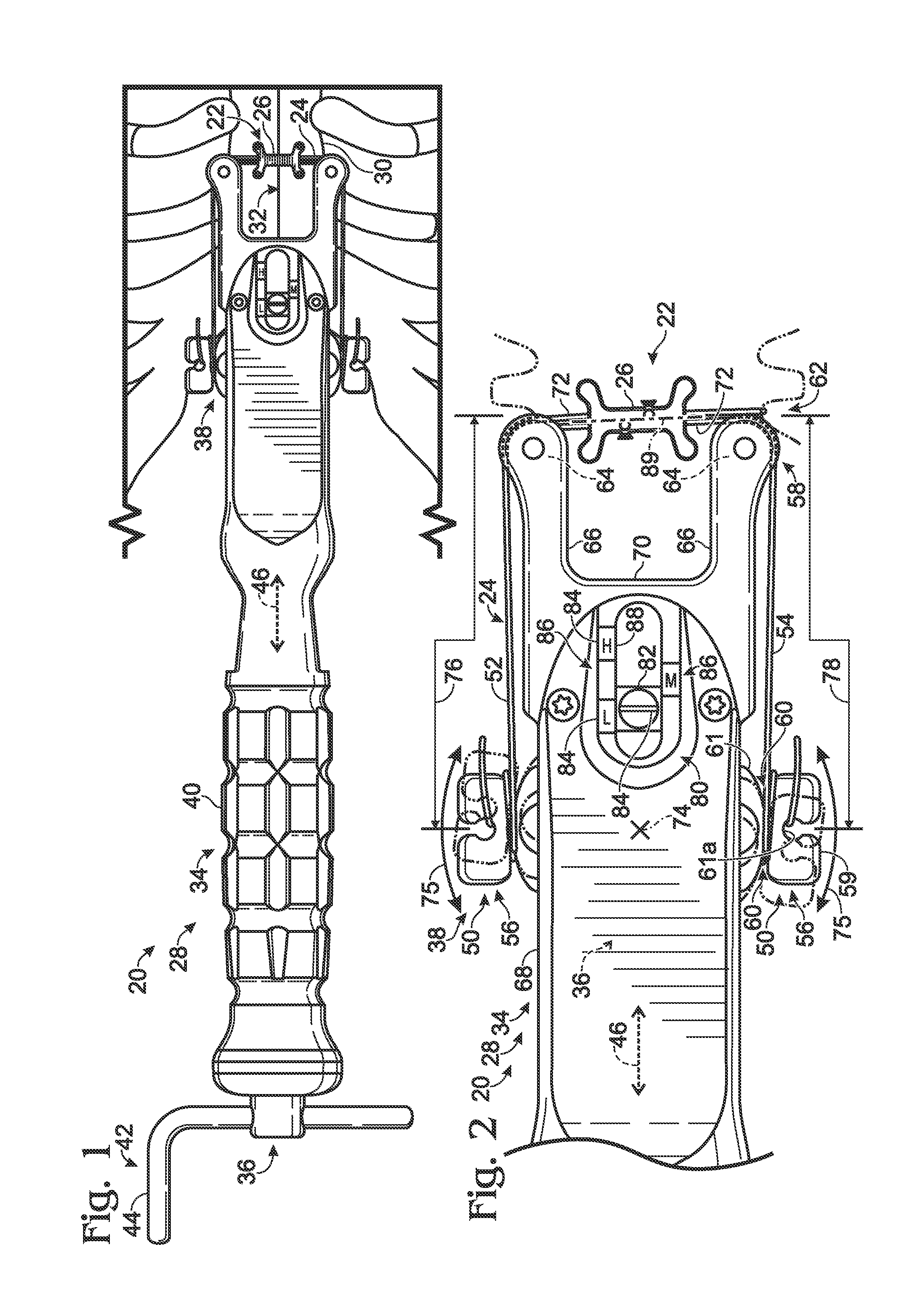
For example, the tensioner may lack a mechanism for equalizing the tension applied to the two ends of the wire, if the wire is unable to slide around bone to equalize tension on its own.
As a result, the wire may dig into and damage bone on one side as the wire is tensioned.
Also, the tensioner may lack any mechanism for measuring the tension applied, or such a mechanism may be present but may be difficult to use effectively during surgery.
Thus, a surgeon may apply too much tension, which may damage bone or break the wire, or may apply too little tension, which may fail to fix the bone properly.
Furthermore, the tensioner may lack a quick and effective mechanism for securing the ends of the wire to the tensioner in a manner that avoids wire slippage as increasing tension is applied.

Method used


Image

  • System for tensioning a surgical wire
  • System for tensioning a surgical wire
  • System for tensioning a surgical wire

Examples


example 1

Tensioner with Dual Tension Gauges

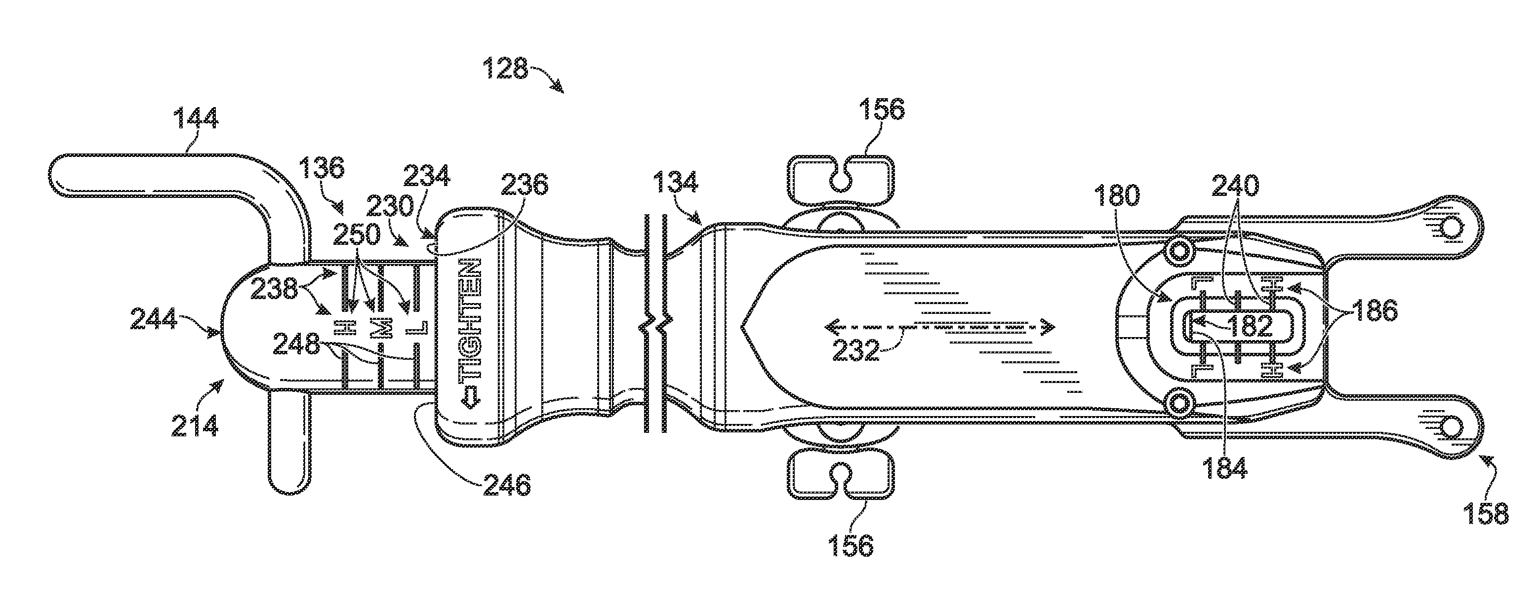
[0061]This example describes an exemplary tensioner 128 equipped with a pair of axially spaced, distal and proximal tension gauges 180, 230; see FIGS. 6 and 7.

[0062]Tensioner 128 of FIGS. 6 and 7 is structurally and functionally similar to tensioner 28 (see FIGS. 1 to 5). Accordingly, to highlight the similarities between the two tensioner embodiments, components of tensioner 128 that are analogous or similar to those of tensioner 28 are identified with reference numbers corresponding to those of tensioner 28, except incremented by 100. For example, tensioner 128 includes a frame 134, a drive assembly 136 including a crank 144 and a drive screw 190, and a carriage 138 supporting hitching brackets 156. Components or features that are absent from tensioner 28, or warrant special mention, are labeled with numeric identifiers starting at 230.

[0063]Tension gauges 180 and 230 are spaced from one another axially, that is, along a long axis 232 defined by t...

example 2

Selected Embodiments

[0073]This example describes selected embodiments of the present disclosure, presented as a series of indexed paragraphs. These embodiments are intended for illustration and should not limit the entire scope of the present disclosure.

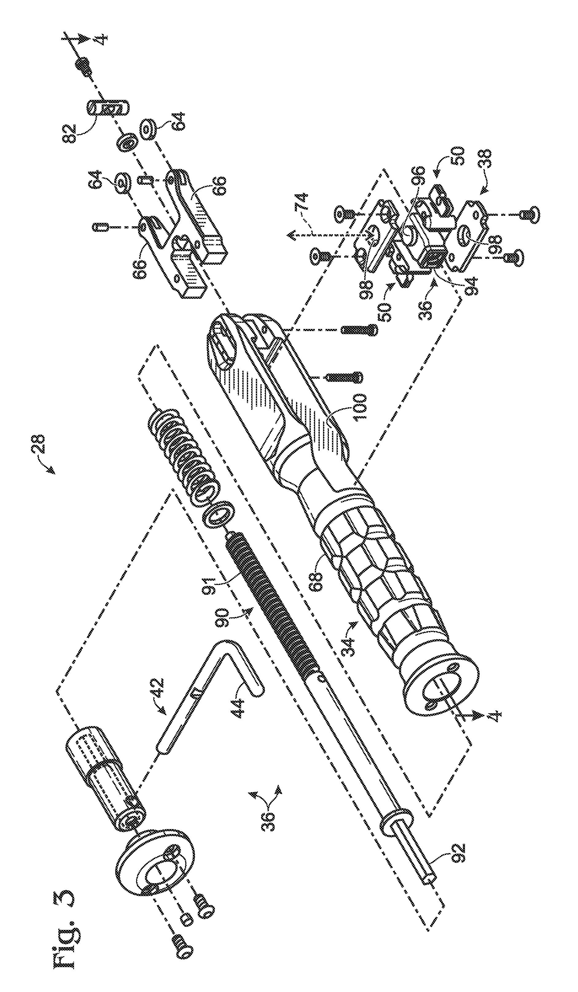
[0074]1. A device for tensioning a surgical wire, comprising: (A) a frame including a distal end portion; (B) a drive assembly connected to the frame and defining an axis of travel; (C) a carriage including opposing anchor sites configured to provide attachment of opposing end regions of a surgical wire extending to the anchor sites from the distal end portion of the frame, the carriage being connected to the drive assembly such that power supplied to the drive assembly drives the carriage away from the distal end portion of the frame, thereby providing an ability to apply tension to both end regions of the wire; and (D) first and second tension gauges formed at spaced positions along the device.

[0075]2. The device of paragraph 1, wh...


PUM


Abstract

System, including methods, apparatus, and kits, for tensioning a surgical wire with a tensioning device and / or fixing bone with a surgical wire tensioned with a tensioning device.

Description

CROSS-REFERENCE TO PRIORITY APPLICATION[0001]This application is based upon and claims the benefit under 35 U.S.C. §119(e) of U.S. Provisional Patent Application Ser. No. 61 / 250,389, filed Oct. 9, 2009, which is incorporated herein by reference in its entirety for all purposes.INTRODUCTION[0002]The human skeleton is composed of 206 individual bones that perform a variety of important functions, including support, movement, protection, storage of minerals, and formation of blood cells. To ensure that the skeleton retains its ability to perform these functions, and to reduce pain and disfigurement, bones that are cut or broken should be repaired promptly and properly. Typically, a cut or broken bone is treated using a fixation device, which reinforces the bone and keeps it aligned during healing. Fixation devices may take a variety of forms, including casts for external fixation and implants (e.g., bone plates, nails, screws, pins, wires, etc.) for internal fixation, among others.[000...

Claims


Application Information

Patent Timeline
Patent Type & Authority Applications(United States)
IPC IPC(8): A61B17/82A61B17/56
CPCA61B17/8869A61B17/823A61B17/8861
Inventor BERNSTEIN, OREN SIMONSONG, HOWARD K.LEGG, ALEXANDER ROBSONGILLARD, JOEL
Owner ACUTE INNOVATIONS
Learn More