Circular stapler introducer with multi-lumen sheath

Inactive Publication Date: 2011-05-19
CILAG GMBH INTERNATIONAL +1
View PDF11 Cites 1467 Cited by
  • Summary
  • Abstract
  • Description
  • Claims
  • Application Information

AI Technical Summary

Problems solved by technology

During such lower colon procedures, it may be difficult to insert the surgical stapler thru the anus and past the transverse folds in the rectal wall that protrude into the colon which are commonly referred to as the “Valves of Houston” and subsequently

Method used


Image

  • Circular stapler introducer with multi-lumen sheath
  • Circular stapler introducer with multi-lumen sheath
  • Circular stapler introducer with multi-lumen sheath

Examples


Example

[0057]The Applicant of the present application also owns the U.S. patent applications identified below which were filed on even date herewith and which are each herein incorporated by reference in their respective entirety:

[0058]U.S. patent application Ser. No. ______, entitled “DEVICES AND METHODS FOR INTRODUCING A SURGICAL CIRCULAR STAPLING INSTRUMENT INTO A PATIENT”, Attorney Docket No. END6320USNP / 090234;

[0059]U.S. patent application Ser. No. ______, entitled “CIRCULAR STAPLER INTRODUCER WITH RIGID CAP ASSEMBLY CONFIGURED FOR EASY REMOVAL”, Attorney Docket No. END6615USNP / 090245;

[0060]U.S. patent application Ser. No. ______, entitled “CIRCULAR STAPLER INTRODUCER WITH RADIALLY-OPENABLE DISTAL END PORTION”, Attorney Docket No. END6616USNP / 090246; and

[0061]U.S. patent application Ser. No. ______, entitled “CIRCULAR STAPLER INTRODUCER WITH RIGID DISTAL END PORTION”, Attorney Docket No. END6617USNP / 090247.

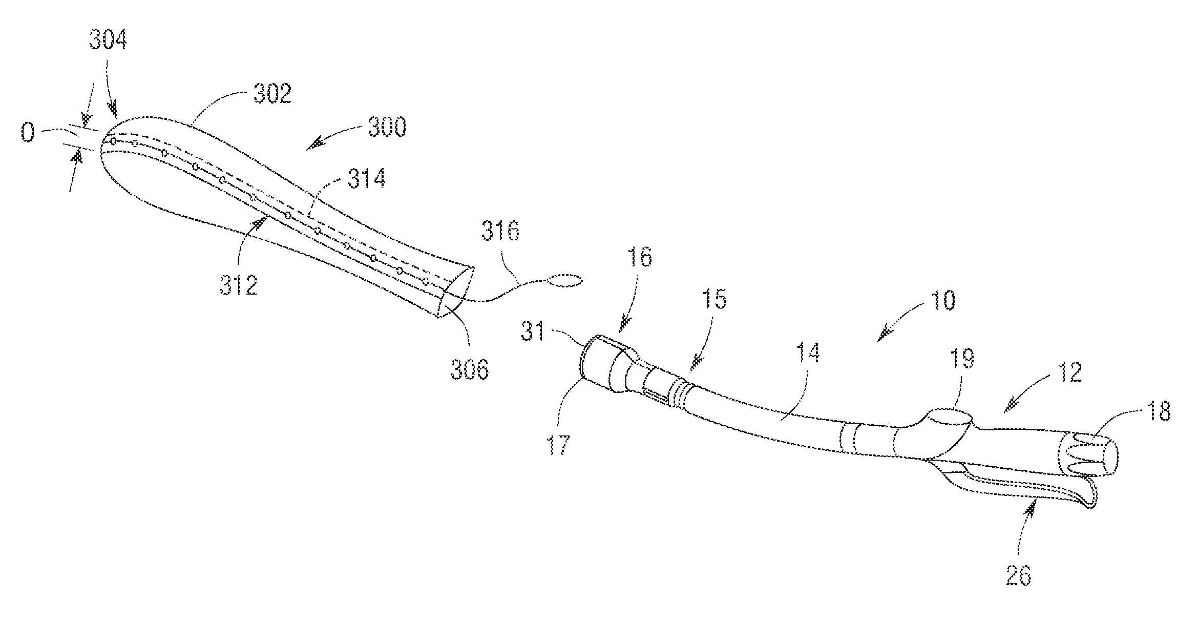
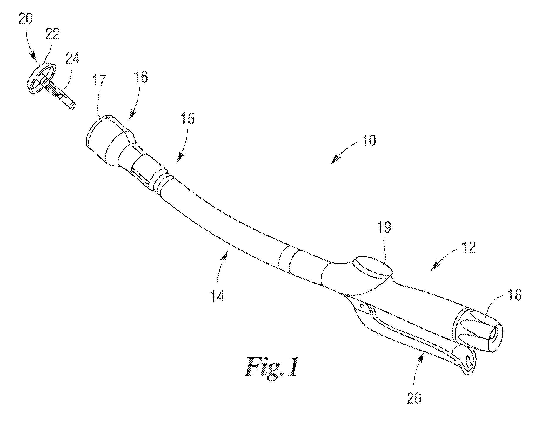
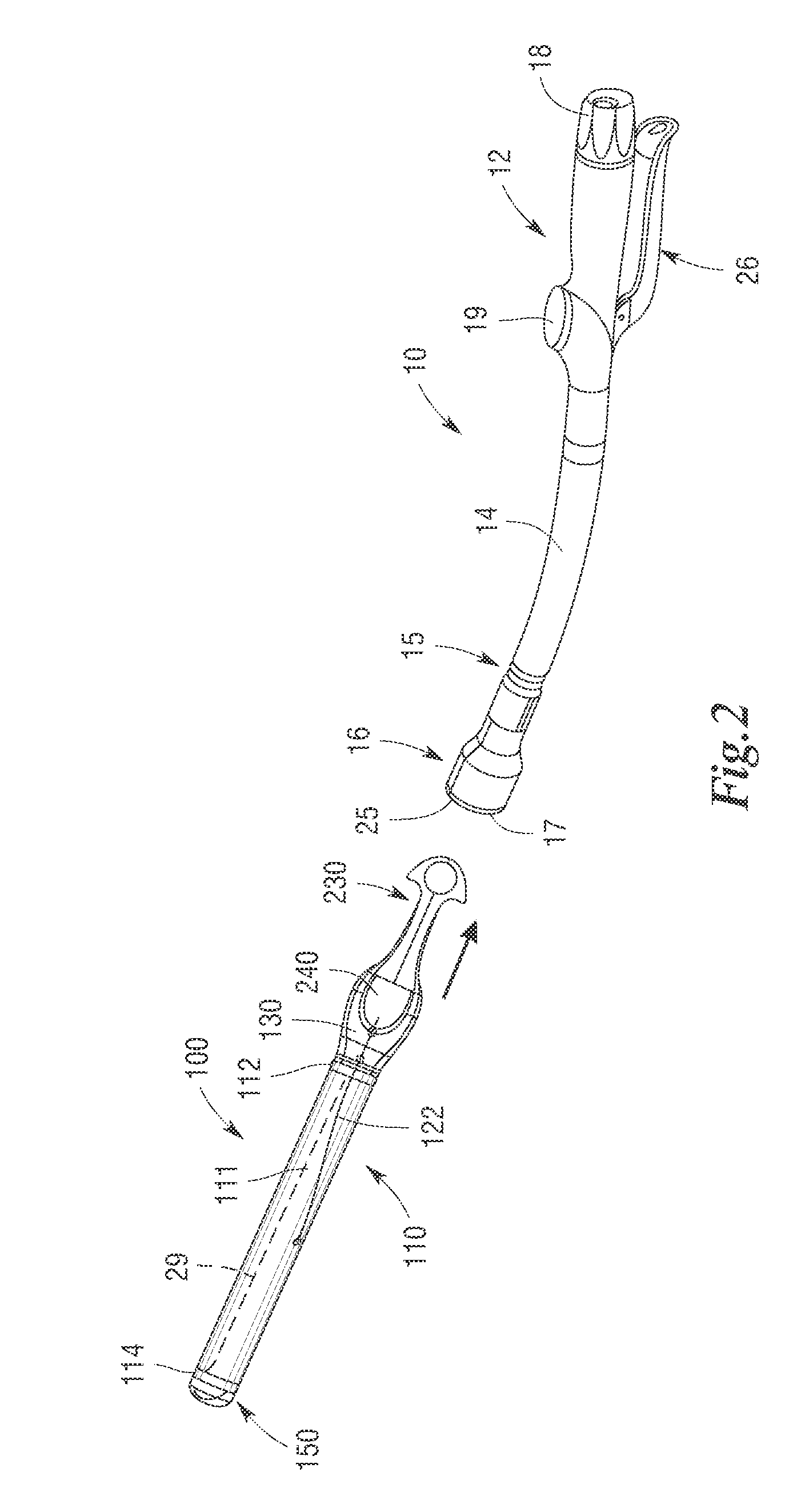
[0062]Certain exemplary embodiments will now be described to provide an overall...


PUM

PropertyMeasurementUnit
Lengthaaaaaaaaaa
Flexibilityaaaaaaaaaa
Areaaaaaaaaaaa

Abstract

Introducers for introducing a surgical circular stapler into a patient. Various embodiments comprise a sheath that defines a first lumen that has a closed end and an open end. The first lumen may be sized to receive at least a distal end portion of the stapling head of the stapler within the closed end. The sheath may have a weakened area therein such that upon an application of a release motion thereto, the weakened area ruptures to permit the hollow sheath to be removed from the stapler.

Description

FIELD OF THE INVENTION[0001]The present invention generally relates to surgical staplers, and more particularly, to devices and methods for introducing a circular stapling device into the colon of a patient.BACKGROUND[0002]In certain types of surgical procedures, the use of surgical staples has become the preferred method of joining tissue and, as such, specially configured surgical staplers have been developed for these applications. For example, intra-luminal or circular staplers have been developed for use in surgical procedures involving the lower colon wherein sections of the lower colon are joined together after a diseased portion has been excised. Circular staplers useful for performing such procedures are disclosed, for example, in U.S. Pat. Nos. 5,104,025; 5,205,459; 5,285,945; and 5,309,927 which are each herein incorporated by reference in their respective entireties.[0003]In general, a conventional circular stapler typically consists of an elongated shaft that has a prox...

Claims


Application Information

Patent Timeline
IPC IPC(8): A61B17/068
CPCA61B17/1114A61B17/115A61B17/1155A61B2019/481A61B2017/00336A61B2019/083A61B2019/307A61B19/081A61B46/10A61B46/13A61B2090/037A61B2090/08021A61B1/00087A61B46/17A61B2017/3425
Inventor BAXTER, III, CHESTER O.HUNT, JOHN V.SILKAITIS, DANIUS P.WILEY, JEFFREY P.FRANER, PAUL T.SCHULTE, JOHN B.ABBOTT, DANIEL J.
Owner CILAG GMBH INTERNATIONAL
Why Eureka
Try Eureka