
Tower with adapter section

a technology of adapter section and tower, which is applied in the field of towers, can solve the problems of difficulty in building and transporting large wind turbine towers, length, weight and diameter of tower components,

Active Publication Date: 2011-06-16
GENERAL ELECTRIC CO
View PDF14 Cites 65 Cited by
  • Summary
  • Abstract
  • Description
  • Claims
  • Application Information

AI Technical Summary

Benefits of technology

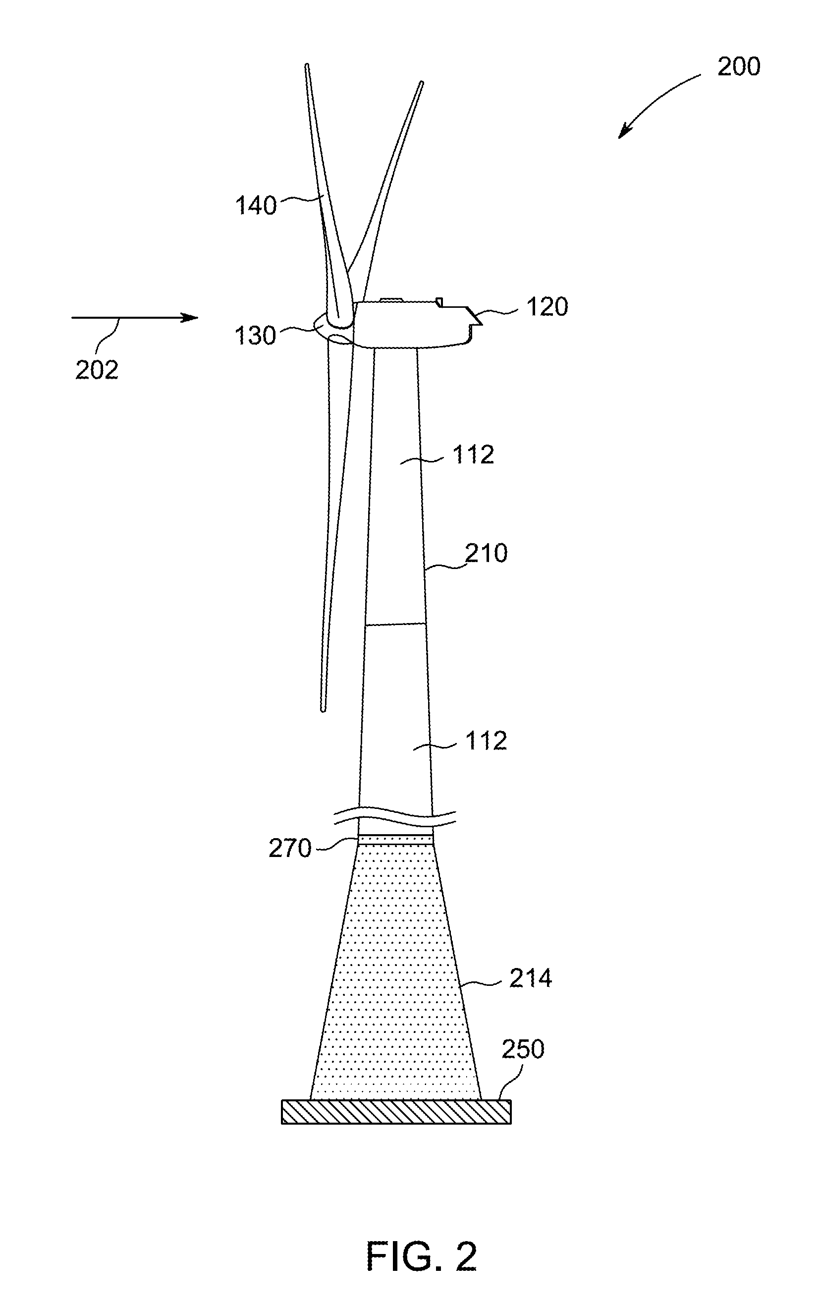
The present invention provides a tower and a wind turbine with a tower that have an adapter section between the concrete tower section and the upper tower section. The adapter section is connected to the upper tower section by a fastening system and to the foundation by a plurality of tensioning cables. The tensioning cables are configured to induce a compressive force on the concrete tower section. The fastening system and the plurality of tensioning cables are substantially vertically aligned so that tower loads are transmitted from the upper tower sections to the tensioning cables. This design ensures efficient transmission of loads and reduces the risk of failure under high wind loads.

Problems solved by technology

However, it becomes difficult to construct and transport large wind turbine towers as the local transportation infrastructure (e.g., roads, bridges, vehicles, etc.) often impose limits on the length, weight and diameter of tower components.

Method used


Image

  • Tower with adapter section
  • Tower with adapter section
  • Tower with adapter section

Examples


Embodiment Construction

[0016]Reference will now be made in detail to the various aspects of the invention, one or more examples of which are illustrated in the figures. Each example is provided by way of explanation of the invention, and is not meant as a limitation of the invention. For example, features illustrated or described as part of one aspect can be used on or in conjunction with other aspects to yield yet a further aspect. It is intended that the present invention includes such modifications and variations.

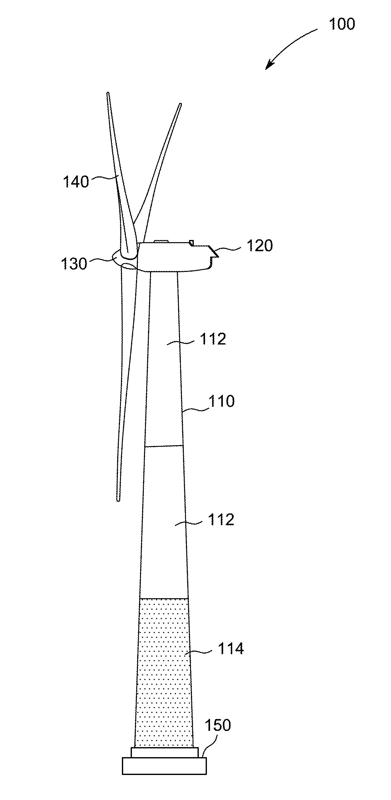
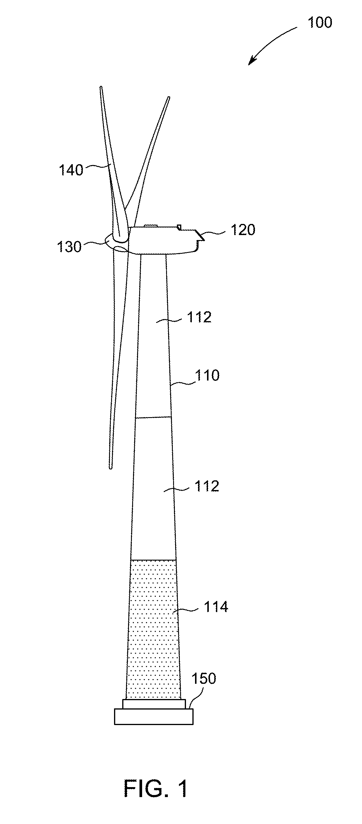
[0017]FIG. 1 shows a wind turbine to which the aspects of the present invention can be advantageously applied. However, it should be understood that the present invention is not limited or restricted to wind turbines but can also be applied to tower structures used in other technical fields. In particular, the various aspects of the present invention may also be applied to antenna towers used in broadcasting or mobile telecommunication or to pylons used in bridge work. Therefore, although the ...


PUM


Abstract

A tower is provided having a foundation, at least one concrete tower section located above the foundation and one or more upper tower sections. An adapter section is located between the concrete tower section and one of the upper tower sections. The adapter section is connected to one of the upper tower sections by a fastening system and to the foundation by a plurality of tensioning cables, which are configured to induce a compressive force on the concrete tower section. The fastening system and the plurality of tensioning cables are substantially vertically aligned so that tower loads are transmitted from the upper tower sections to the plurality of tensioning cables.

Description

BACKGROUND OF THE INVENTION[0001]This invention relates generally to towers. In particular, but not limited thereto, the present invention relates to wind turbine towers having an adapter between steel and concrete sections.[0002]Recently, wind turbines have received increased attention as environmentally safe and relatively inexpensive alternative energy sources. With this growing interest, considerable efforts have been made to develop wind turbines that are reliable and efficient.[0003]Generally, a wind turbine includes a rotor having multiple blades. The rotor is mounted to a housing or nacelle, which is positioned on top of a truss or tubular tower. Utility grade wind turbines (i.e., wind turbines designed to provide electrical power to a utility grid) can have large rotors (e.g., 30 or more meters in diameter). Blades on these rotors transform wind energy into a rotational torque or force that drives one or more generators that may be rotationally coupled to the rotor through ...

Claims


Application Information

Patent Timeline
Patent Type & Authority Applications(United States)
IPC IPC(8): E04H12/02E02D27/50E04C5/12
CPCE02D27/42E04H12/085E04C5/125E02D27/425E04H12/12E04H12/16Y02E10/728
Inventor BAGEPALLI, BHARAT SAMPATHKUMARAN
Owner GENERAL ELECTRIC CO
Learn More