Twin-actuator configuration for a camera module

Inactive Publication Date: 2011-06-16
DIGITAL IMAGING SYST
View PDF7 Cites 6 Cited by
  • Summary
  • Abstract
  • Description
  • Claims
  • Application Information

AI Technical Summary

Benefits of technology

[0018]In accordance with the objects of this invention a camera module having a movable lens barrel, allowing a maximum lens diameter with minimal outside dimensions has been achieved. The camera module invented comprises a movable lens barrel, at least two actuators to move said lens barrel, wherein each actuator is deployed in a separate corner of the camera module, and a means to guide the movements of the lens barrel.

Problems solved by technology

It is a challenge for the designers of camera modules to develop auto-focus camera modules using one or more actuators to move a lens barrel having minimal size.

Method used


Image

  • Twin-actuator configuration for a camera module
  • Twin-actuator configuration for a camera module
  • Twin-actuator configuration for a camera module

Examples


first embodiment

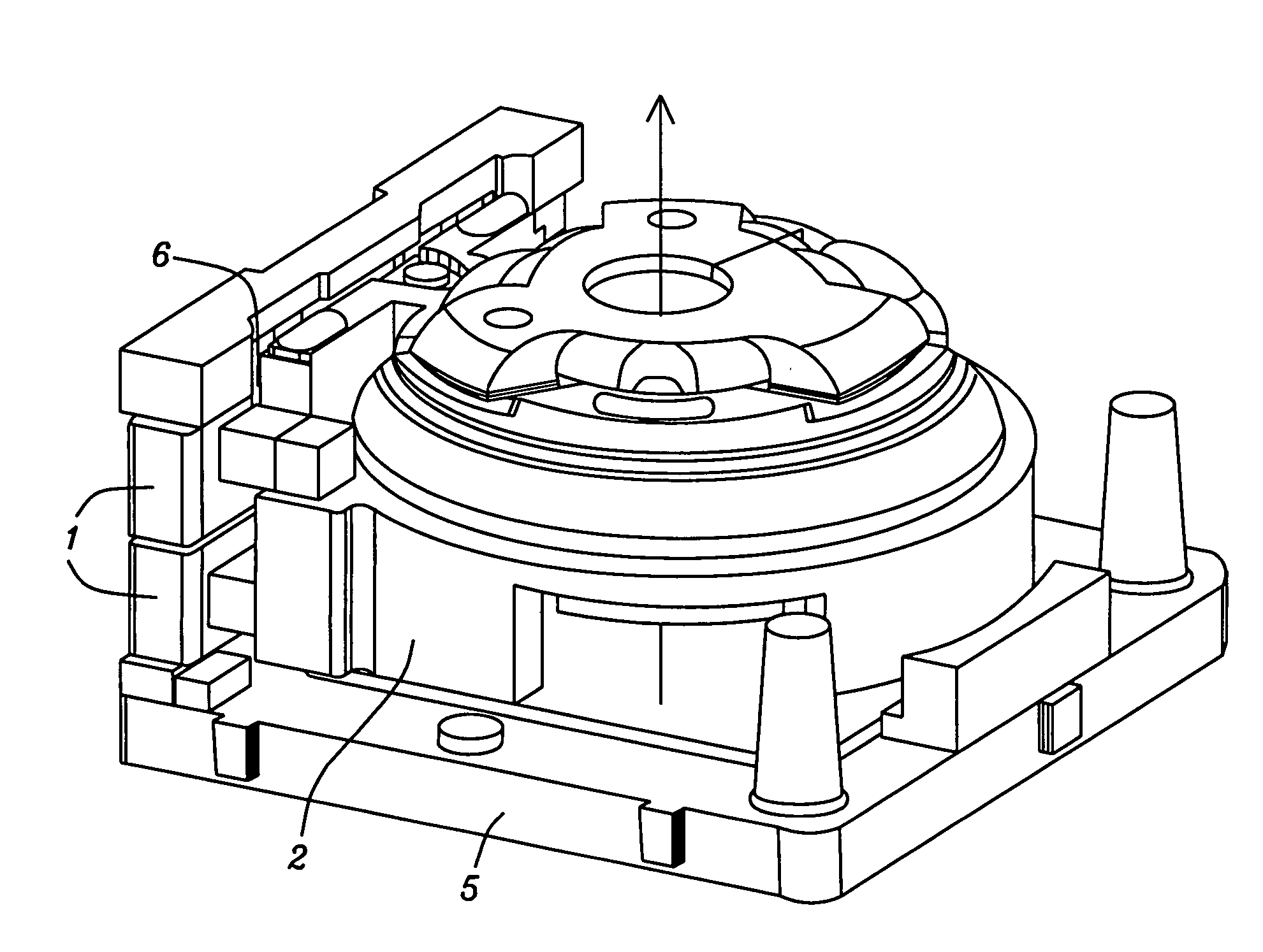
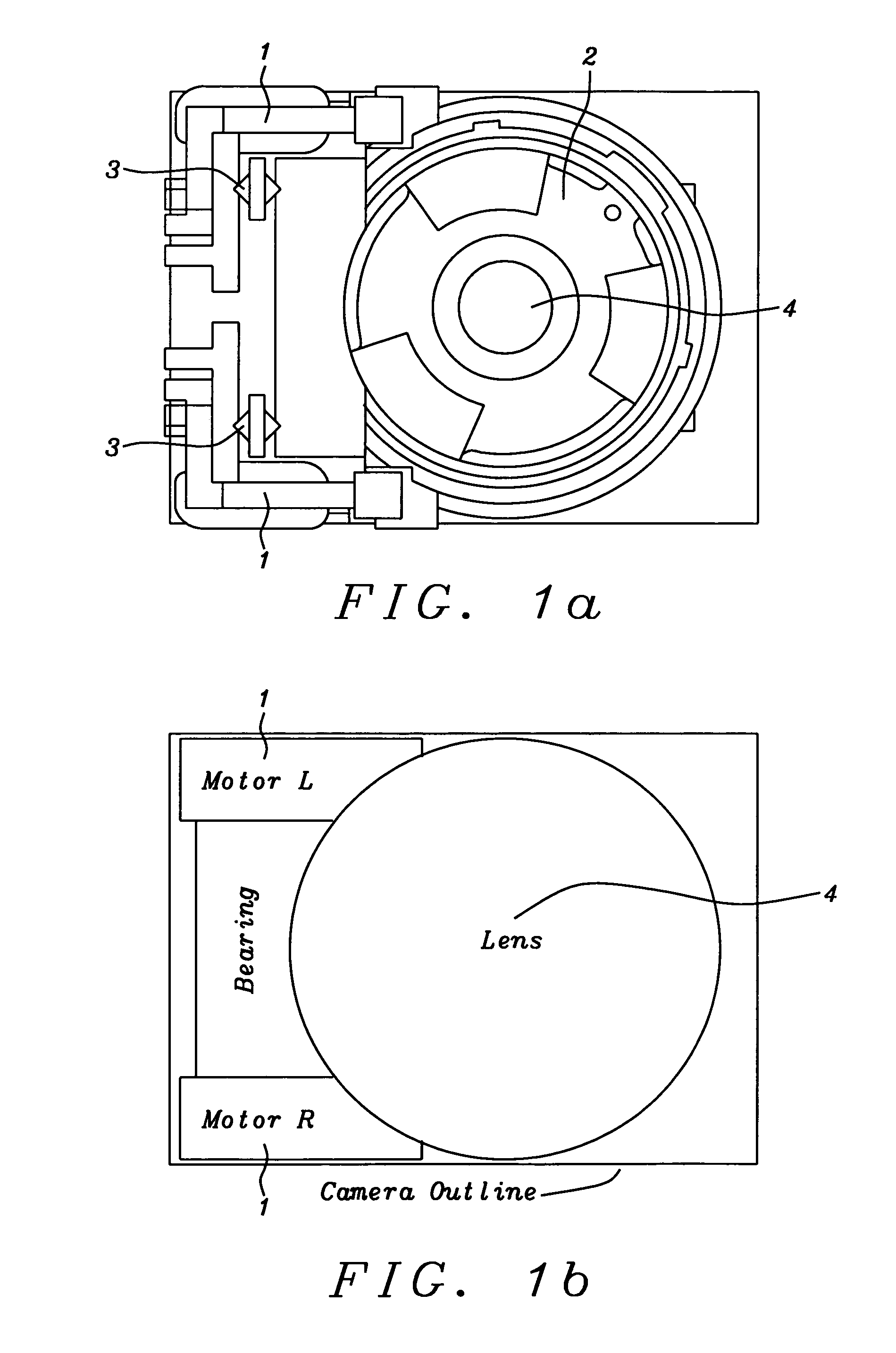
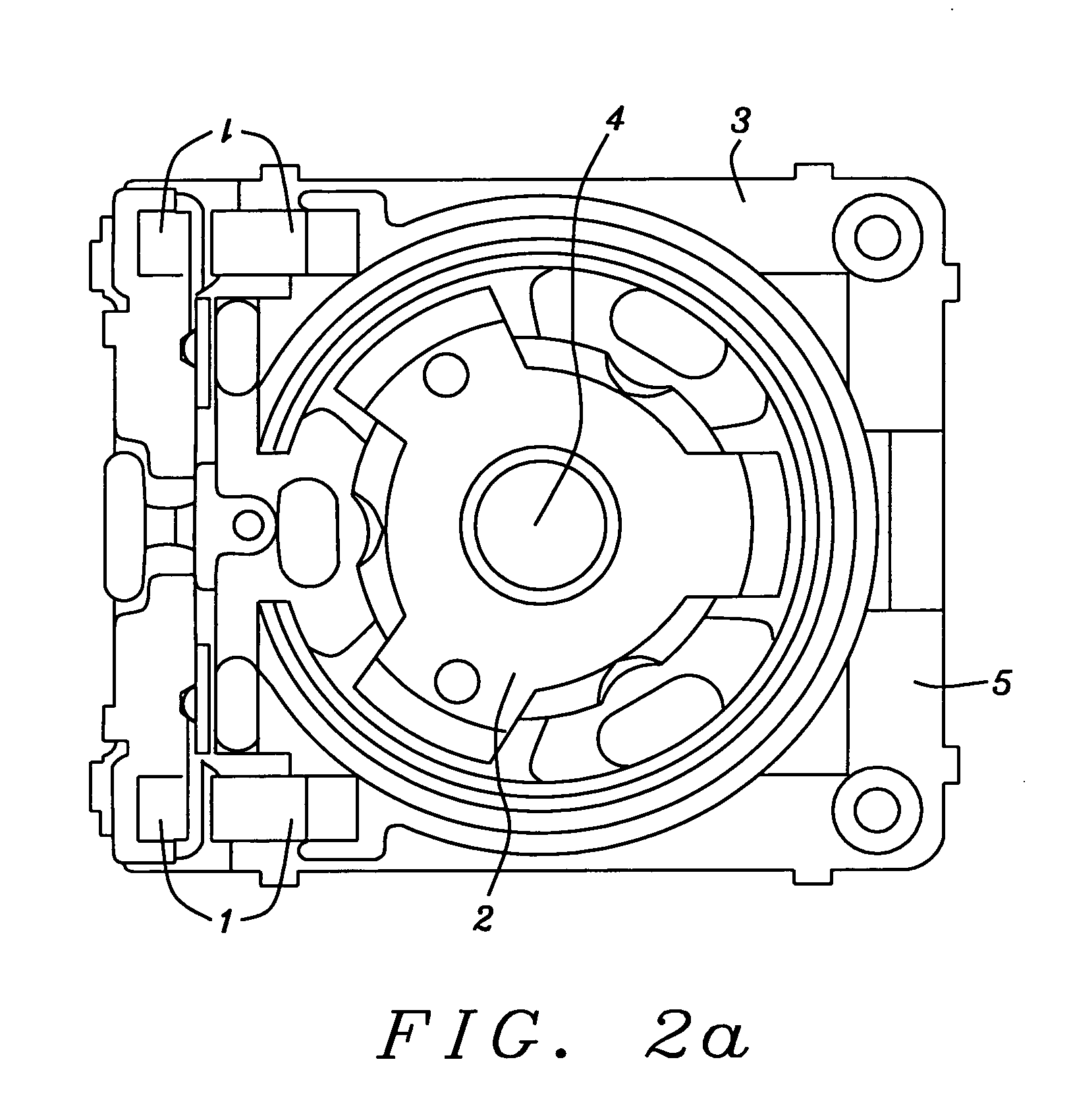
[0031]FIG. 1a shows a top view of the present invention. It shows two identical actuators 1. Identical actuators are preferable but they could be of different types as long as they have a same torque. Furthermore it shows a movable lens barrel 2, which is moved by the two actuators 1 and guided by two ball bearings 3 to achieve minimal friction of the movement of the lens barrel and a carrier 5. The lens barrel 2 is moving up and down with respect to the carrier 5. The ball bearing system 3 is guiding the lens barrel 2 containing the lens 4. The twin actuators 1 can be smaller of size than a single actuator and fit into the corners of the camera module with minimum extra space requirement because the lens and lens barrel are round and the camera module is rectangular.

[0032]FIG. 1b shows key points of the first embodiment of the present invention. The right and left motors / actuators 1 are deployed in the corners on the same side as the ball bearings, thus minimizing the space require...

second embodiment

[0036]FIGS. 3a-c show the present invention. Guiding rods, diagonally located at two corners, guide the movable lens barrel. Two preferably identical actuators are located also diagonally at the other corners of the camera module. Adjusting springs can be applied to the guiding rods.

[0037]FIG. 3a shows an assembled camera module with a movable lens barrel 2, fixed parts 5, guiding rods 30, being diagonally deployed, and two bidirectional actuators comprising coils 32, which are firmly connected to fixed parts 5 of the camera module, and magnets 33, which are firmly connected to the movable lens barrel 2. The two actuators are also diagonally deployed. Depending upon the currents flowing through the coils 32, the magnets 33 are moved inside the coils 32. Each of the two guiding rods 30 and each of the two actuators are deployed in a separate corner of the camera module.

[0038]FIG. 3b shows fixed parts 5 with diagonally located guiding rods 30, springs 31 and diagonally deployed actuat...


PUM


Abstract

Systems and methods for camera modules having a movable lens barrel, allowing a maximum lens diameter with minimal outside dimensions are disclosed. At least two actuators are moving the lens barrel. Each actuator is deployed in a separate corner of the camera module. In a first embodiment of the invention two actuators are deployed on a same side of the camera module having ball bearings between them. In a second embodiment two actuators are diagonally deployed having guiding rods deployed on the other corners of the camera module.

Description

RELATED APPLICATION[0001]This application is related to the following US patent application:[0002]DI08-006, titled “Camera Shutter and position control thereof”, Ser. No. 12 / 658,280, filing date Feb. 5, 2010 and is assigned to the same assignee.[0003]The content of this application is hereby incorporated by reference in their entirety.BACKGROUND OF THE INVENTION[0004](1) Field of the Invention[0005]This invention relates generally to camera modules and relates more specifically to camera modules having a movable lens barrel and wherein the actuators are deployed in a way to achieve minimal size of the camera module.[0006](2) Description of the Prior Art[0007]Digital camera modules are used with many electronic devices such as e.g. mobile phones, personal data assistants (PDAs), computers, etc. These camera modules have to be as small as possible, reliable and easy to be used, robust and require minimal power consumption. Furthermore the design of the camera modules should allow low ...

Claims


Application Information

Patent Timeline
Patent Type & Authority Applications(United States)
IPC IPC(8): G02B7/02
CPCG02B13/001G02B7/08
Inventor SCHWORM, ERNSTBARTENSCHLAGER, GABRIEL
Owner DIGITAL IMAGING SYST
Why Eureka
Try Eureka