

Wide-angle zoom lens system
a wide-angle zoom and lens technology, applied in the field of wide-angle zoom lens systems, can solve the problems of insufficiently achieving the wide angle of view at the short focal length extremity, and no consideration has been taken in substantial ways to reduce the lens diameter, which tends to be larger
- Summary
- Abstract
- Description
- Claims
- Application Information
AI Technical Summary
Benefits of technology
Problems solved by technology
Method used
Image

Examples
embodiment 1
[Embodiment 1]
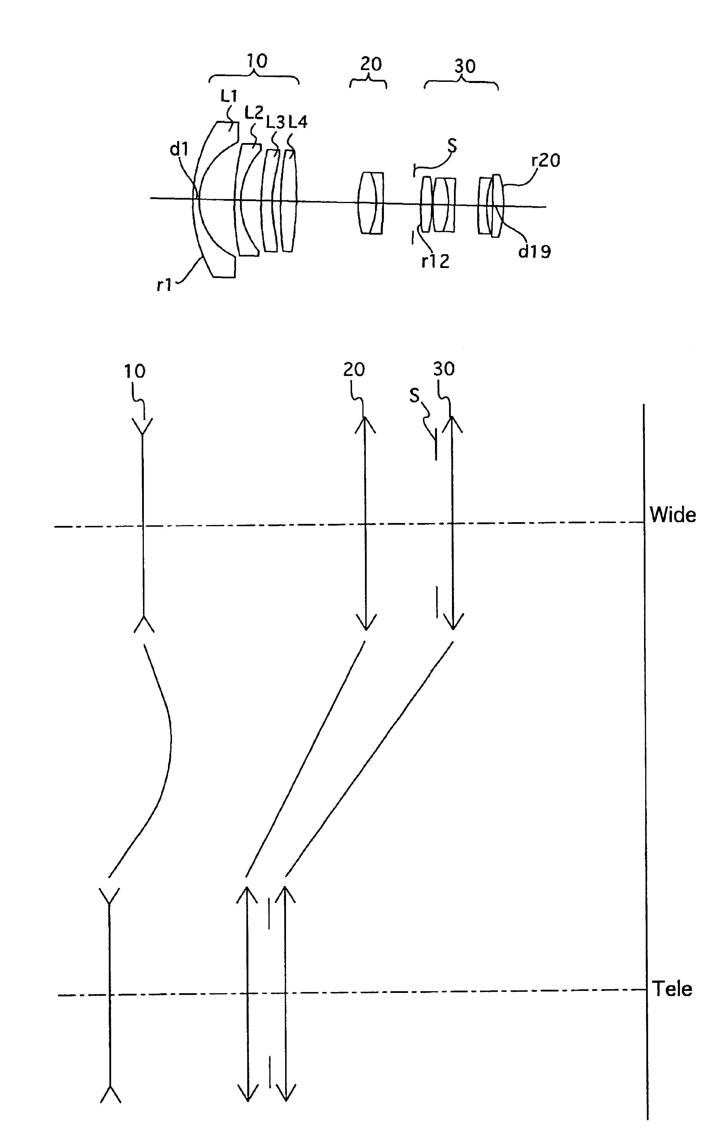
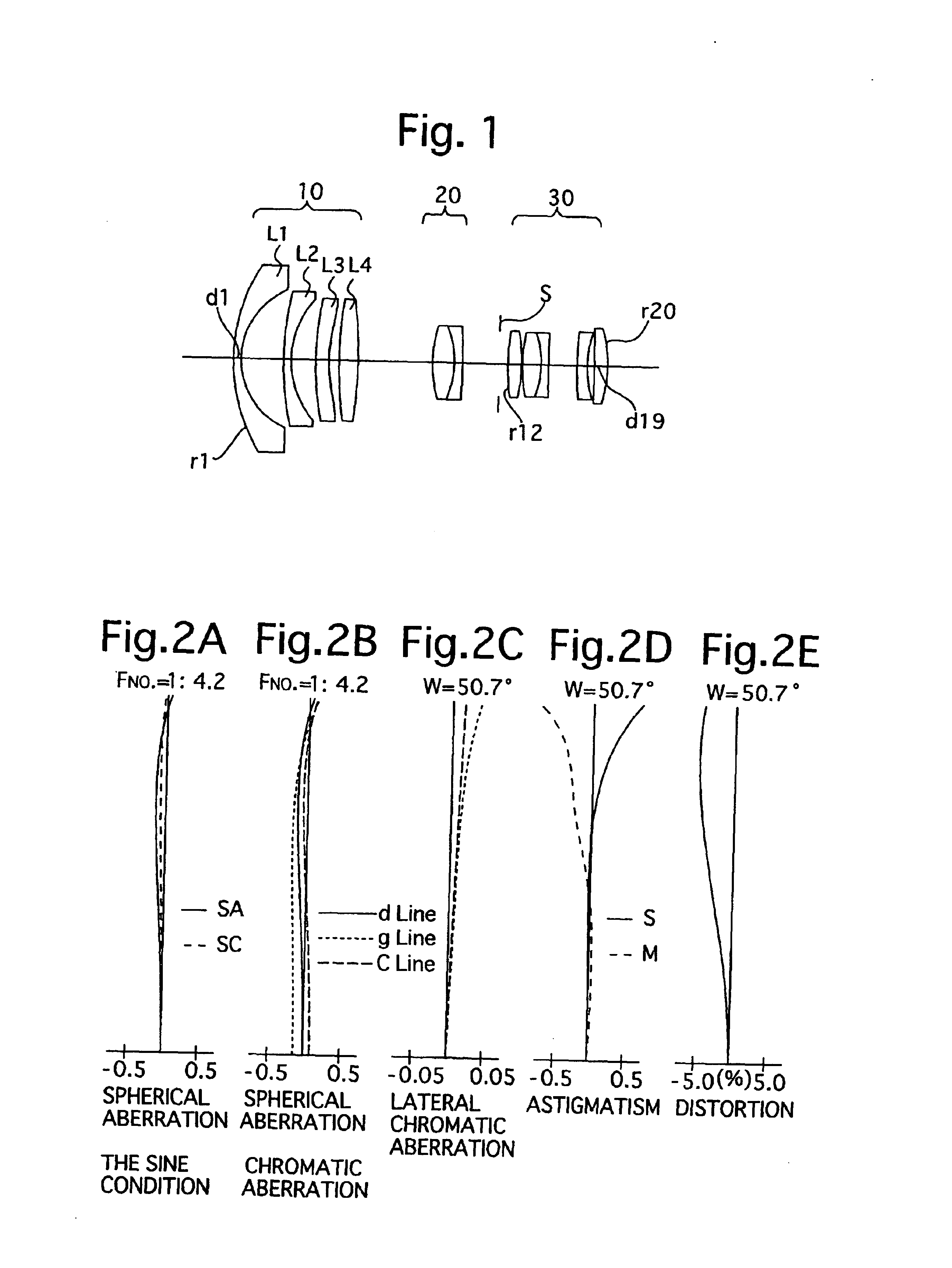
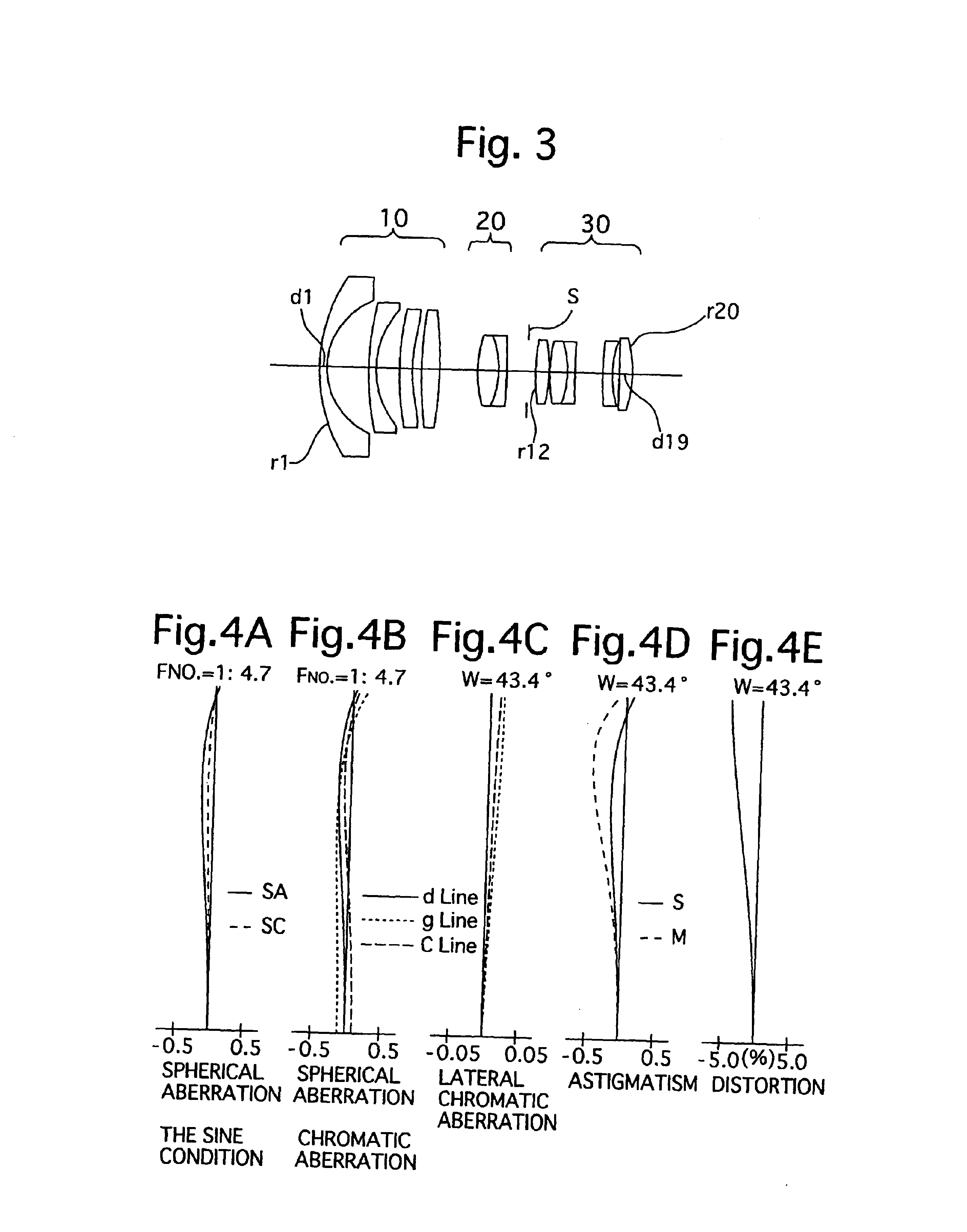
FIG. 1 is a lens arrangement, at the short focal length extremity, of the wide-angle zoom lens system according to the first embodiment of the present invention. FIGS. 2A through 2E show aberrations occurred in the lens arrangement shown in FIG. 1. FIG. 3 is a lens arrangement, at an intermediate focal length extremity, of the wide-angle zoom lens system according to the first embodiment. FIGS. 4A through 4E show aberrations occurred in the lens arrangement shown in FIG. 3. FIG. 5 is a lens arrangement, at the long focal length extremity, of the wide-angle zoom lens system according to the first embodiment. FIGS. 6A through 6E show aberrations occurred in the lens arrangement shown in FIG. 5. Table 1 shows the numerical data of the first embodiment. The diaphragm S is provided 1.70 from the object side of the positive third lens group 30 (in front of surface No. 12).
TABLE 1FNO. = 1:4.2 - 4.7 - 5.8f = 18.50 - 23.99 - 33.99W = 50.7 - 43.4 - 33.2fB = 37.00 - 44.61 - 58.19...
embodiment 2
[Embodiment 2]
FIG. 7 is a lens arrangement, at the short focal length extremity, of the wide-angle zoom lens system according to the second embodiment of the present invention. FIGS. 8A through 8E show aberrations occurred in the lens arrangement shown in FIG. 7. FIG. 9 is a lens arrangement, at an intermediate focal length extremity, of the wide-angle zoom lens system according to the second embodiment. FIGS. 10A through 10E show aberrations occurred in the lens arrangement shown in FIG. 9. FIG. 11 is a lens arrangement, at the long focal length extremity, of the wide-angle zoom lens system according to the second embodiment. FIGS. 12A through 12E show aberrations occurred in the lens arrangement shown in FIG. 11. Table 2 shows the numerical data of the second embodiment. The diaphragm S is provided 1.70 from the object side of the third lens group 30 (in front of surface No. 12).
TABLE 2FNO. = 1:4.3 - 4.9 - 5.8f = 18.50 - 24.16 - 33.99W = 50.8 - 43.3 - 33.4fB = 37.00 - 45.17 - 58.7...
embodiment 3
[Embodiment 3]
FIG. 13 is a lens arrangement, at the short focal length extremity, of the wide-angle zoom lens system according to the third embodiment of the present invention. FIGS. 14A through 14E show aberrations occurred in the lens arrangement shown in FIG. 13. FIG. 15 is a lens arrangement, at an intermediate focal length extremity, of the wide-angle zoom lens system according to the third embodiment. FIGS. 16A through 16E show aberrations occurred in the lens arrangement shown in FIG. 15. FIG. 17 is a lens arrangement, at the long focal length extremity, of the wide-angle zoom lens system according to the third embodiment. FIGS. 18A through 18E show aberrations occurred in the lens arrangement shown in FIG. 17. Table 3 shows the numerical data of the third embodiment. The diaphragm S is provided 1.70 from the object side of the third lens group 30 (in front of surface No. 12).
TABLE 3FNO. = 1:4.2 - 4.7 - 5.8f = 18.50 - 24.00 - 33.96W = 50.8 - 43.4 - 33.3fB = 37.00 - 44.72 - 58...
PUM
 Abstract
Description
Claims
Application Information