Exterior Rearview Mirror for Motor Vehicles

a technology for rearview mirrors and motor vehicles, applied in optical viewing, optical instruments, optics, etc., can solve the problem of difficult positioning of auxiliary mirrors with regard to primary mirrors

Active Publication Date: 2011-06-30
SMR PATENTS S A R L
View PDF7 Cites 19 Cited by
  • Summary
  • Abstract
  • Description
  • Claims
  • Application Information

AI Technical Summary

Problems solved by technology

Positioning of the auxiliary mirror with regard to the primary mirror is difficult and requires precision to ensure that the field of view for each of the mirrors or reflective surfaces are aligned properly to maximize the ability of the user to increase the field of view rearward of the motor vehicle.

Method used


Image

  • Exterior Rearview Mirror for Motor Vehicles
  • Exterior Rearview Mirror for Motor Vehicles
  • Exterior Rearview Mirror for Motor Vehicles

Examples


Embodiment Construction

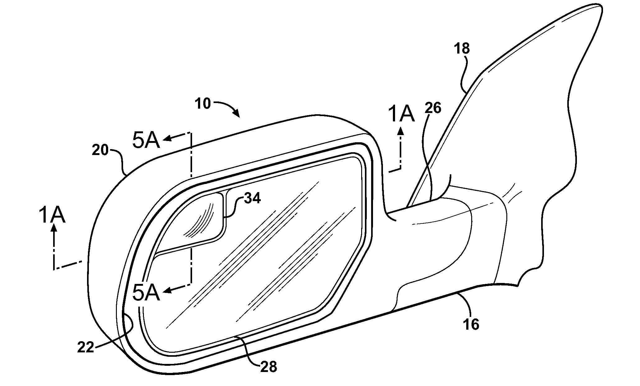
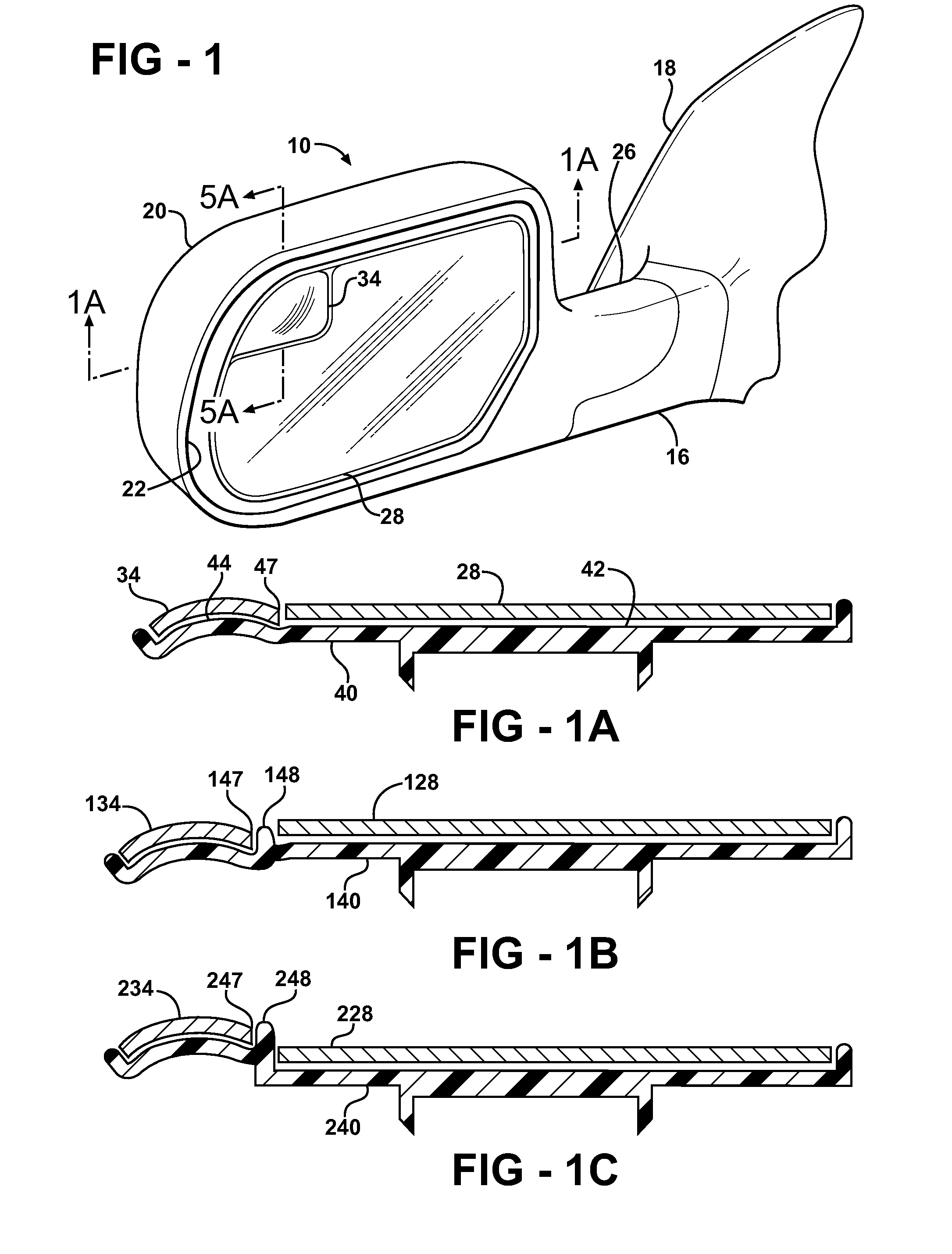
[0018]Referring to FIG. 1, an exterior rearview mirror assembly is generally indicated at 10. The exterior rearview mirror assembly 10 is fixedly secured to a motor vehicle 12 on a side 14 thereof. This is best seen in FIG. 4. While only one exterior rearview mirror assembly 10 is shown, it should be appreciated by those skilled in the art that a second exterior rearview mirror assembly 10 may be fixedly secured to a side opposite the side 14 of the motor vehicle 12.

[0019]The exterior rearview mirror assembly 10 includes a bracket, graphically represented in FIGS. 1 and 4 by a bracket cover 16. The bracket 16 is mounted to the side 14 of the motor vehicle 12. The mounting thereof is covered by a sail 18, which is an aesthetic piece that also is able to improve the aerodynamics of the exterior rearview mirror assembly 10.

[0020]The exterior rearview mirror assembly 10 also includes a mirror casing 20. The mirror casing 20 is secured to the bracket 16. The mirror casing 20 defines a pr...


PUM


Abstract

An exterior rearview mirror assembly for a motor vehicle is disclosed having a primary mirror and a spotting mirror. Both the primary mirror and the spotting mirror are secured to the same single mirror support, or backing plate. The spotting mirror is snap fit to the backing plate by having a monolithic structure which is receivable by a recess or hole in the backing plate. The recess acts as a securing device by receiving an abutment surface extending outwardly away from the monolithic structure which snaps over the backing plate and prevents the spotting mirror from moving away from the backing plate.

Description

[0001]This patent application is a continuation-in-part of a U.S. patent application Ser. No. 11 / 968,989, filed on Jan. 3, 2008, the disclosure of which is hereby expressly incorporated by reference.BACKGROUND ART[0002]1. Field of the Invention[0003]The invention relates to exterior rear view mirror assemblies for motor vehicles. More particularly, the invention relates to exterior rear view mirror assemblies that include a plurality of mirrors with differing fields of view.[0004]2. Background of the Invention[0005]Multiple mirrors in a rear view mirror assembly are common. The multiple mirrors include a primary mirror and what is typically referred to as a secondary or spotting mirror. This secondary reflector is located somewhere adjacent the primary reflective surface and is used to aid the user of the motor vehicle to increase his field of view around the motor vehicle.[0006]The spotter mirror is typically curved to increase the field of view rearward of the motor vehicle. Posit...

Claims


Application Information

Patent Timeline
Patent Type & Authority Applications(United States)
IPC IPC(8): B60R1/08
CPCB60R1/081
Inventor HENION, PAUL R.SINELLI, GARY J.
Owner SMR PATENTS S A R L
Why Eureka
Try Eureka