Miter detent override mechanism

Active Publication Date: 2011-07-07
CREDO TECH CORP +1
View PDF7 Cites 9 Cited by
  • Summary
  • Abstract
  • Description
  • Claims
  • Application Information

AI Technical Summary

Problems solved by technology

Many known mechanisms are difficult to locate on the saw, so much so that many users are completely unaware of the feature.

Method used


Image

  • Miter detent override mechanism
  • Miter detent override mechanism
  • Miter detent override mechanism

Examples


Embodiment Construction

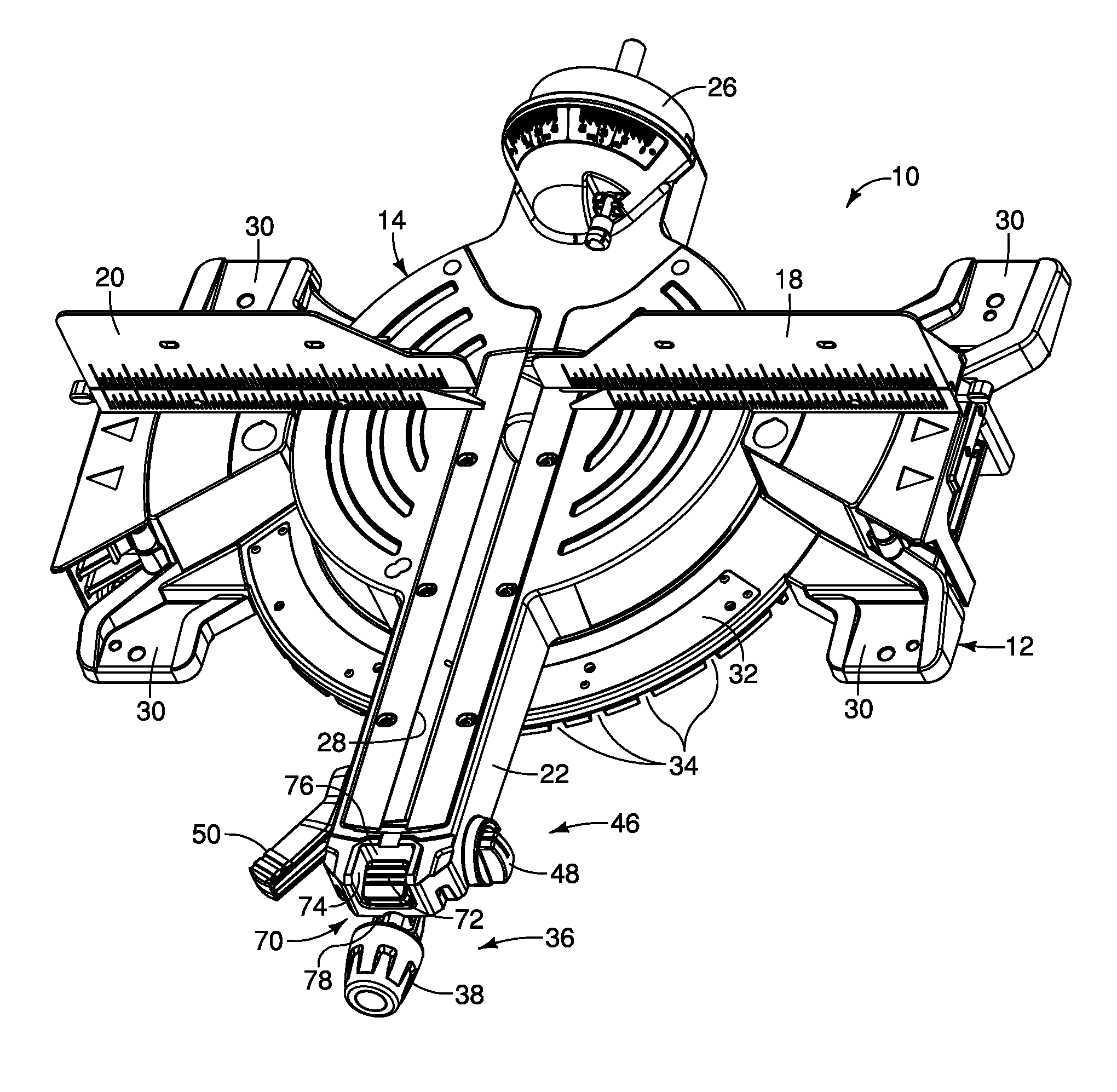
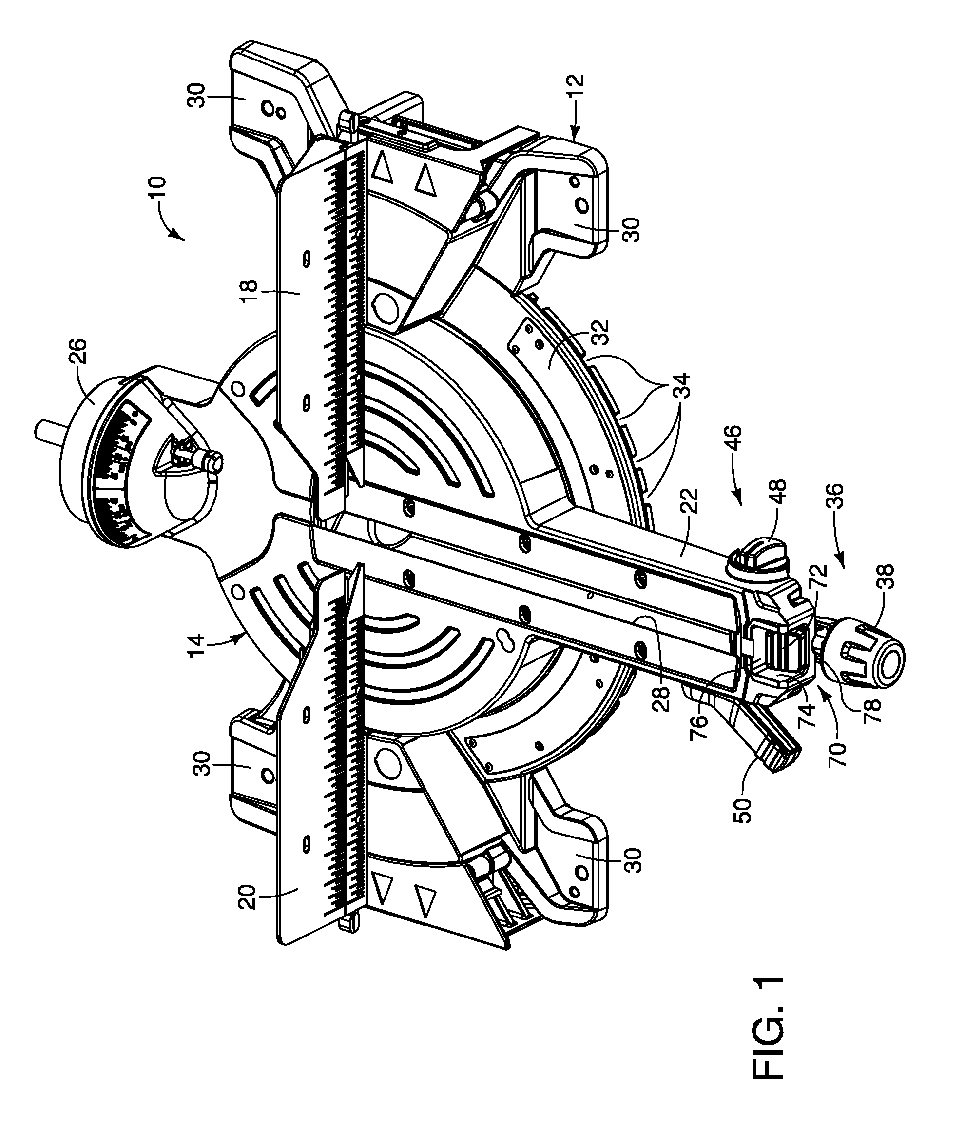
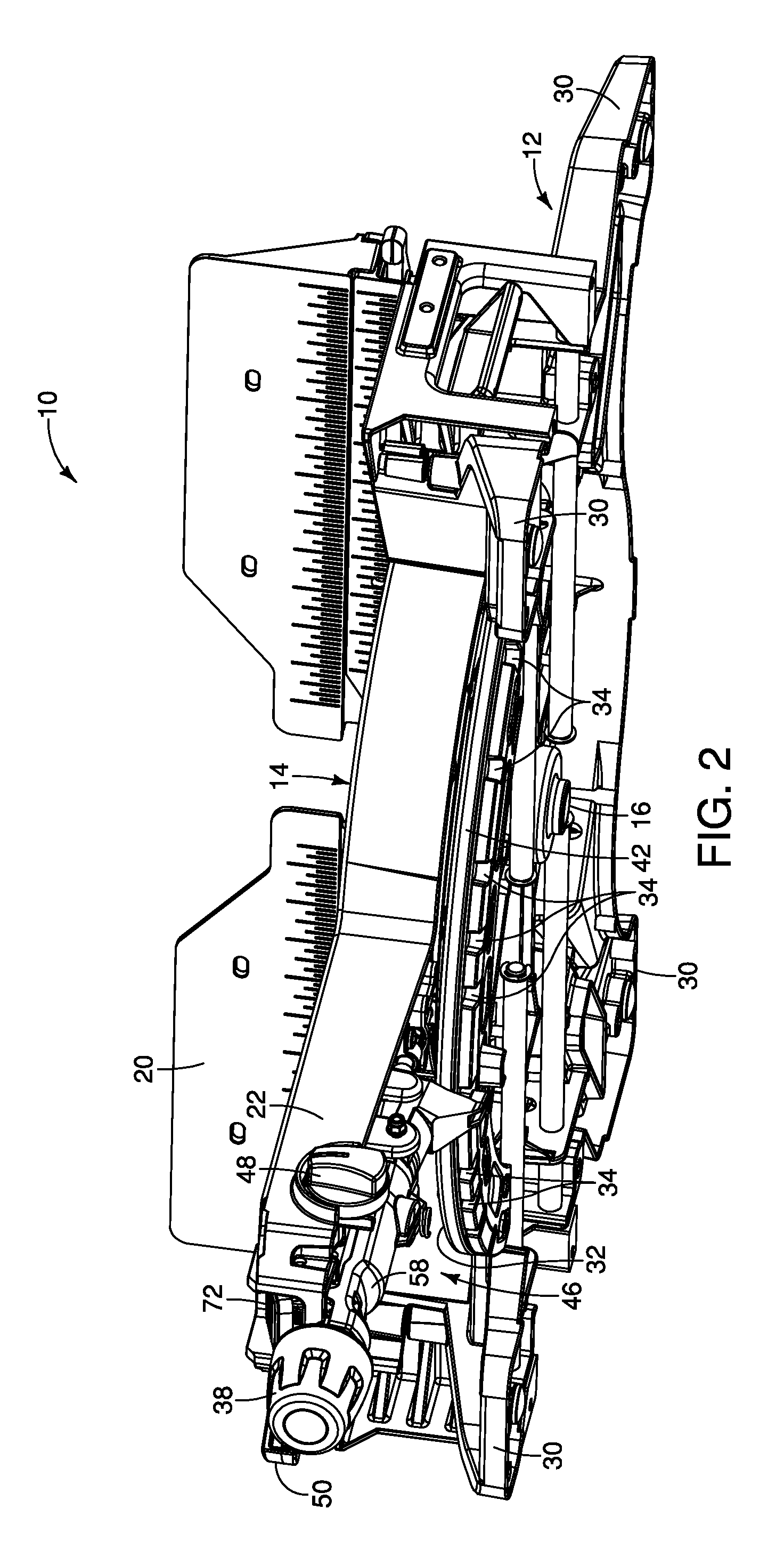
Embodiments of the present invention are directed to a miter saw having a detent override system which provides a new way to disengage a miter detent system of a power miter saw. The controls for the override system have been designed and configured to be in the line of sight of a user and the operative controls for engaging the override system is significantly larger than most known systems. The miter detent system as well as the detent override system is designed and configured to be conveniently operated by a user using only one hand.

Turning now to the drawings, and particularly FIGS. 1 and 2, components of a power miter saw are illustrated and are indicated generally at 10. The saw 10 includes a base, indicated generally at 12, as well as a rotatable table, indicated generally at 14, that is rotatable thereon about a horizontal pivot connection 16 as shown in FIG. 2. The saw has fence sections 18 and 20 that are attached to the base 12. The table 14 has a front extension 22 that...


PUM

PropertyMeasurementUnit
Lengthaaaaaaaaaa
Distanceaaaaaaaaaa

Abstract

Embodiments of the invention are directed to a miter saw comprising a base with a plurality of detents, a rotatable table mounted to the base, the table having a front handle portion configured to enable a user to angularly adjust the position of the table relative to the base, a detent system mounted to the table and comprising a moveable lever with a gripping portion and a detent pin on the opposite end thereof selectively engaging the detents, and a detent override mechanism for retaining the lever and detent pin out of engagement with the detents, the override mechanism comprising a moveable button positioned on the top of the handle portion, whereby a user can grasp the handle portion and gripping portion with one hand and move the button with the thumb to retain the lever and associated detent pin out of engagement with any of the detents.

Description

BACKGROUND OF THE INVENTIONThe present invention generally relates to power miter saws.Most miter saws provide the user with a set of predetermined miter angles that define commonly used angles in carpentry. The angles are typically defined by a set of detents in the base of the miter saw. A moveable detent pin housed in the rotating table of the miter saw selectively engages the detents to angularly position the table at a desired angle.In certain cases, it is desirable to disengage the miter detent system. This is most commonly desired when a cut needs to be made at an angle that is close to a specific detent defined angle. For example, if the user attempts to set the saw one degree away from the forty-five degree detent, the detent system often pulls the saw back to forty-five degrees. This happens because more than half of the detent pin is aligned with the forty-five degree detent. The spring force on the pin moves the saw back to the detent.To overcome this problem, many miter...

Claims


Application Information

Patent Timeline
IPC IPC(8): B23D47/02B23D45/04
CPCB23D47/00Y10T83/7697Y10T83/7722
Inventor THOMAS, ADAM S.
Owner CREDO TECH CORP
Why Eureka
Try Eureka