System and method for proppant transfer

a proppant and transfer system technology, applied in the direction of transportation items, passenger handling equipment, borehole/well accessories, etc., can solve the problems of high attrition rate, increased risks associated with dry proppant, time-consuming procurement and transportation of proppant to and from offshore production platforms,

Active Publication Date: 2011-07-07
SHCLUMBERGER NORGE AS
View PDF12 Cites 86 Cited by
  • Summary
  • Abstract
  • Description
  • Claims
  • Application Information

AI Technical Summary

Benefits of technology

[0011]In another aspect, embodiments disclosed herein relate to a method of transferring proppant materials as a dense phase, the method including conveying pneumatically, a slug comprising proppant materials from a first pressurized container to a second pressurized container and filtering the proppant materials to remove dust from one or more of the first pressurized container and the second pressurized container.

Problems solved by technology

In addition to requiring numerous crane lifts, procurement and then transportation of proppant to and from an offshore production platform may also be time consuming.
In addition to the time consuming nature of existing transportation mechanisms of proppant, proppant is inherently dangerous, and the transportation of proppant may increase the risks associated with the dry proppant.
However, such methods result in a high attrition rate, damage the resin coating on the proppant materials, and create more dust particles.
Increased resin dust particles from the proppant may, over a certain concentration, result in an explosion, if ignited.
Thus, the vacuum methods of transferring proppant may further increase the dangers of transferring proppant.
While wetting the proppant causes the particles to stick together, thereby decreasing the amount of dust produced, the wetting also decreases the effectiveness of the proppant when constituted into a fluid prior to injection into the wellbore.
Thus, operators are typically faced with choosing between a slow dangerous process of transferring proppant using multiple crane lifts, or decreasing the effectiveness of the end product.

Method used


Image

  • System and method for proppant transfer
  • System and method for proppant transfer
  • System and method for proppant transfer

Examples


Embodiment Construction

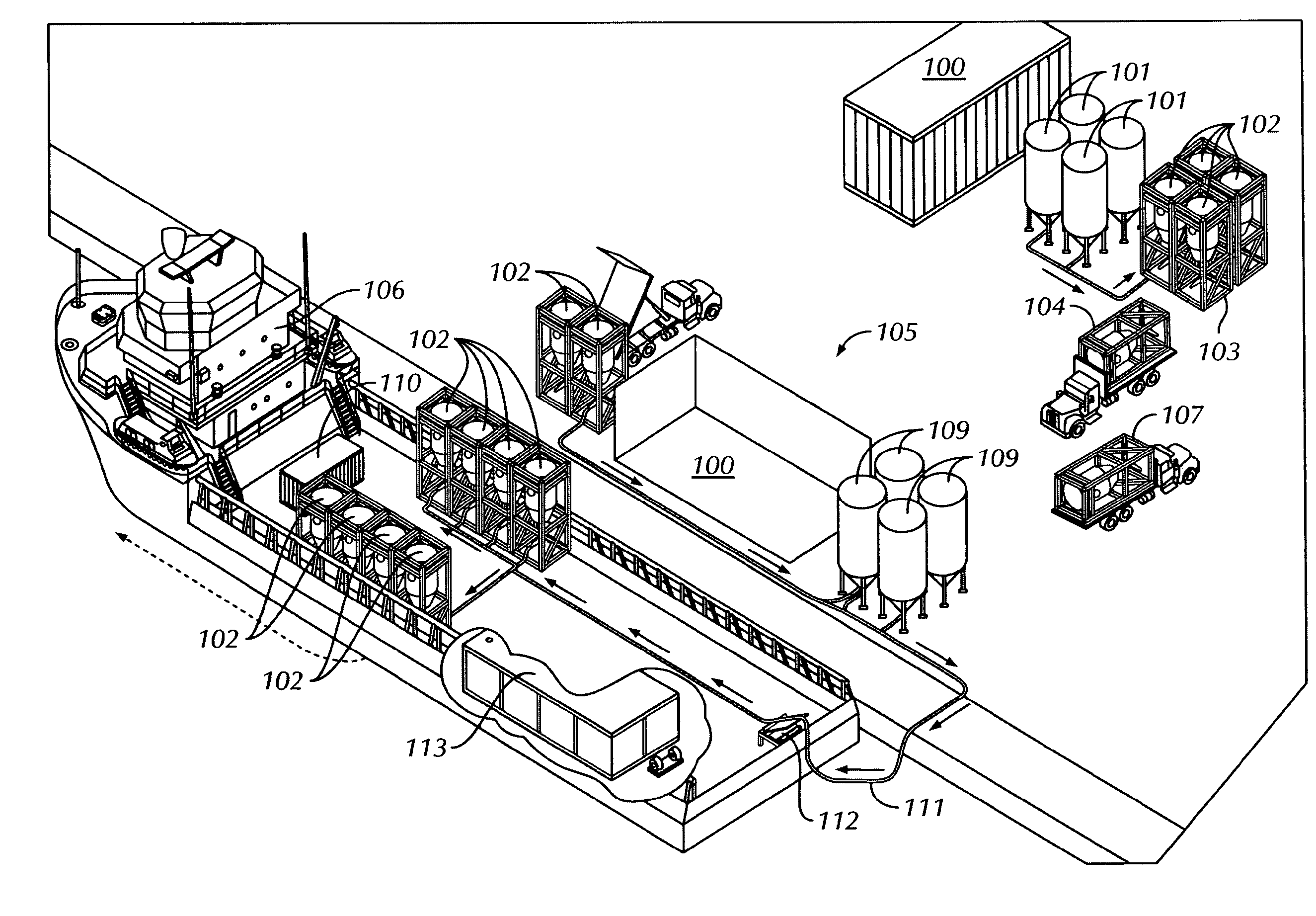
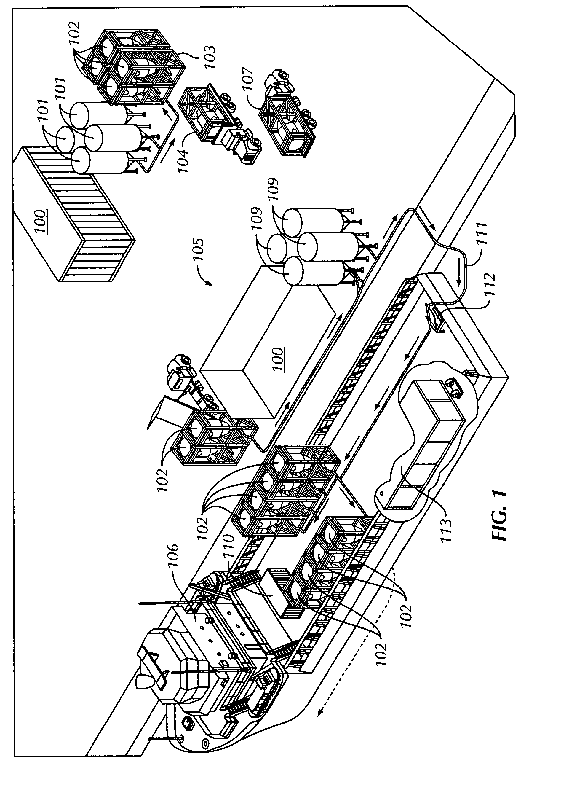
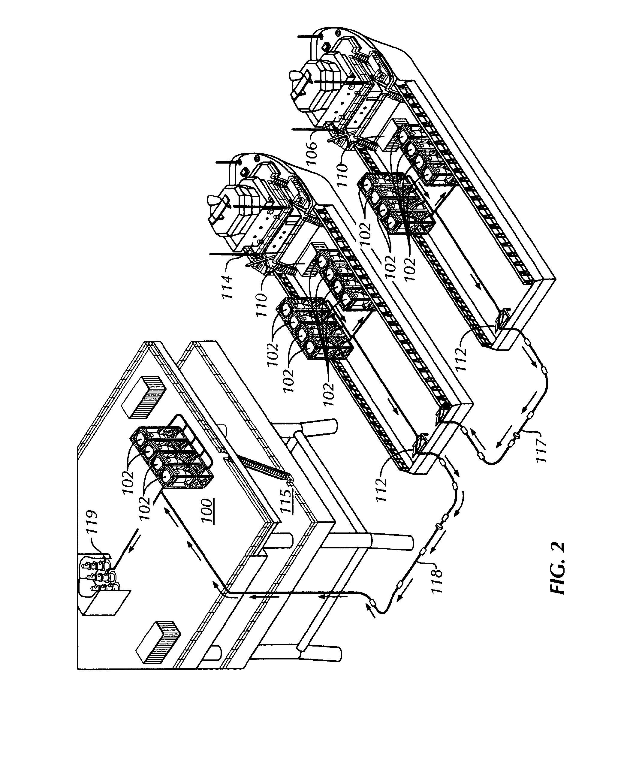
[0022]In one aspect, embodiments disclosed herein relate to methods and systems for transferring proppant materials between pressurized containers. More specifically, embodiments disclosed herein relate to methods and systems for transferring proppant materials between pressurized containers as a dense phase. More specifically still, embodiments disclosed herein relate to methods and systems for transferring proppant materials between pressurized containers disposed on supply vessels, stimulation vessels, and offshore production platforms.

[0023]Generally, proppant materials are transferred from supply vessels to stimulation vessels, where the proppant materials are mixed with water and chemicals to create fluid for injection into a wellbore. Typically, the transfer of such proppant materials may occur through the transportation of box or bags on stimulation vessels via gravity tanks and conveyor belts, where the proppant materials are mixed, and then transferred or pumped to an offs...


PUM


Abstract

A method of transferring proppant materials, wherein the method includes providing a first pressurized container (102) containing proppant materials on a first vessel (106). The method also includes connecting the first pressurized container (102) on the first vessel (106) to a second container (102) on a second vessel (114) and transferring pneumatically, proppant materials from the first pressurized container (102) on the first vessel (106) to the second container (102) on the second vessel (114). Also, a method of transferring proppant materials, the method including removing a wellbore fluid comprising excess proppant materials from a well, and screening the excess proppant materials from the wellbore fluid. The method also includes transferring the excess proppant materials to a first pressurized container (102) and transferring pneumatically, the excess proppant materials from the first pressurized container to a second pressurized container.

Description

BACKGROUND[0001]1. Field of the Disclosure[0002]Embodiments disclosed herein relate generally to methods and systems for transferring proppant materials between pressurized containers. More specifically, embodiments disclosed herein relate to methods and systems for transferring proppant materials between pressurized containers as a dense phase. More specifically still, embodiments disclosed herein relate to methods and systems for transferring proppant materials between pressurized containers disposed on supply vessels, stimulation vessels, and offshore production platforms.[0003]2. Background Art[0004]Traditionally, methods of transferring dry material, including proppant materials from land-based facilities to boats and then to offshore production platforms, includes lifting box or bags or bags of dry material from a first location to a second location with a crane. Depending on the volume of proppant required for a specific operation the number of crane lifts and boat trips may ...

Claims


Application Information

Patent Timeline
Patent Type & Authority Applications(United States)
IPC IPC(8): E21B43/00B65G53/12B63B27/24
CPCB65G53/12B63B27/20E21B21/066B63B27/29E21B21/065
Inventor MACKENZIE, JOHNWRIGHT, PETEREIA, JAN THORE
Owner SHCLUMBERGER NORGE AS
Why Eureka
Try Eureka