Synchronous pumping of a wagon wheel optical cavity

a wagon wheel and optical cavity technology, applied in the direction of optical resonator shape and construction, laser details, electrical equipment, etc., can solve the problems of not finding a way to apply similar circular bragg reflectors, most rudimentary mode control, and difficult coupling of whispering modes for useful work, etc., to achieve low optical absorption and inexpensive fabrication

Inactive Publication Date: 2011-07-07
HILLIARD DONALD B
View PDF5 Cites 0 Cited by
  • Summary
  • Abstract
  • Description
  • Claims
  • Application Information

AI Technical Summary

Benefits of technology

[0063]Another object of the present invention is to provide a laser cavity mirror with low optical absorpti...

Problems solved by technology

These microdisk and microsphere lasers are very effective in cases involving evanescent coupling to an adjacent dielectric structure; however, they are known to contain a very large number of competing high-order modes.
In addition, the coupling of these whispering modes for useful work is difficult for applications not utilizing evanescent coupling.
However, none of these studies are found to address the issues of applying similar circular Bragg reflectors...

Method used


Image

  • Synchronous pumping of a wagon wheel optical cavity
  • Synchronous pumping of a wagon wheel optical cavity
  • Synchronous pumping of a wagon wheel optical cavity

Examples


Embodiment Construction

[0078]The following description and FIGS. 1-2 of the drawings depict various embodiments of the present invention. The embodiments set forth herein are provided to convey the scope of the invention to those skilled in the art. While the invention will be described in conjunction with the preferred embodiments, various alternative embodiments to the structures and methods illustrated herein may be employed without departing from the principles of the invention described herein. Like numerals are used for like and corresponding parts of the various drawings.

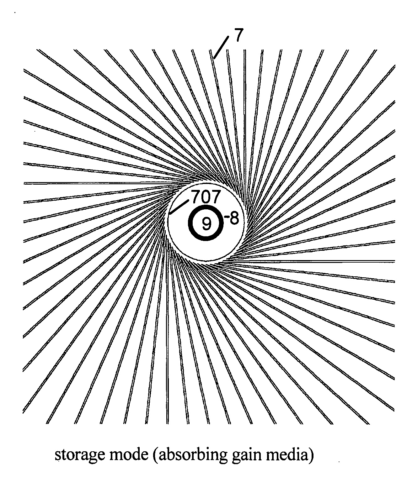
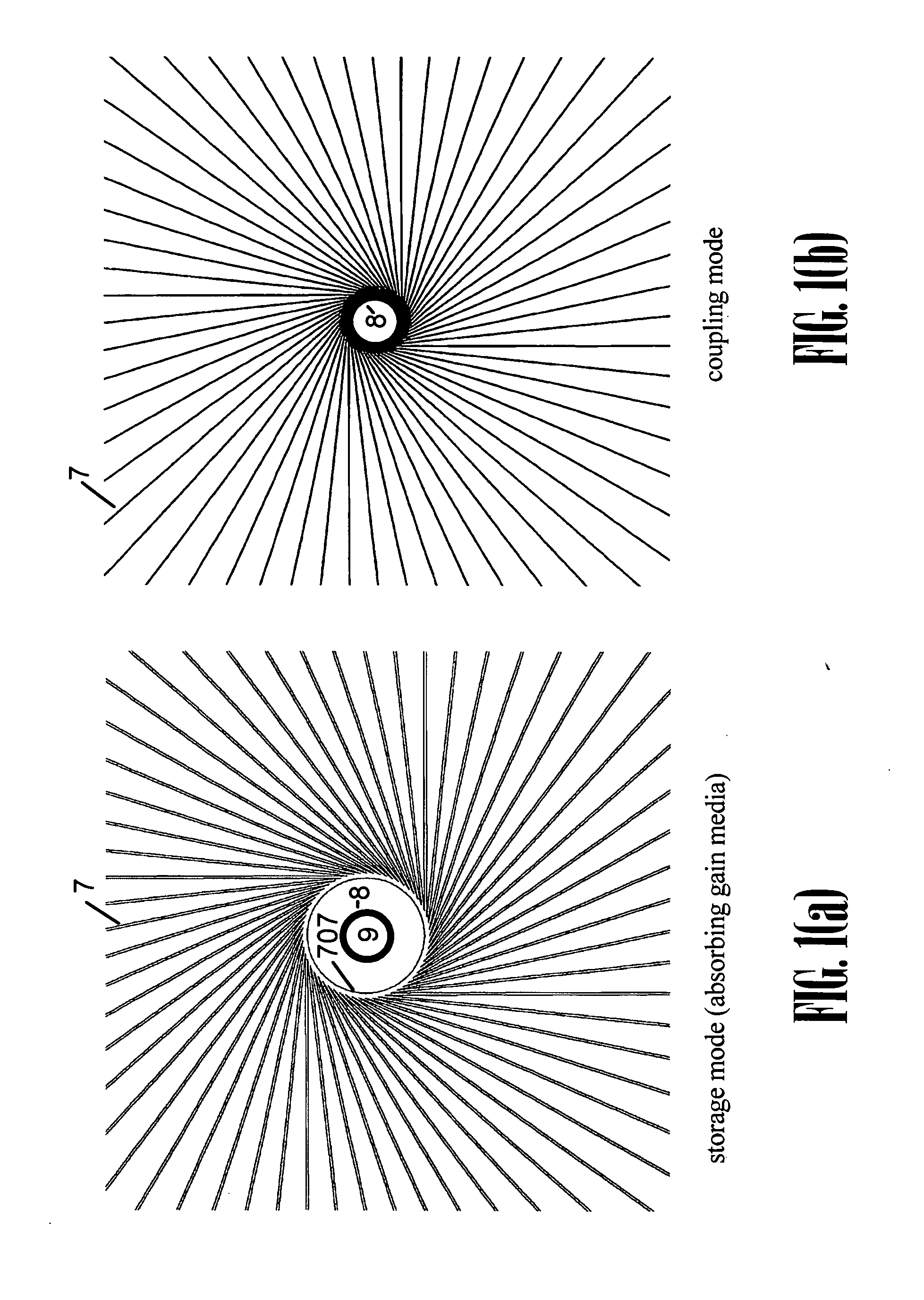
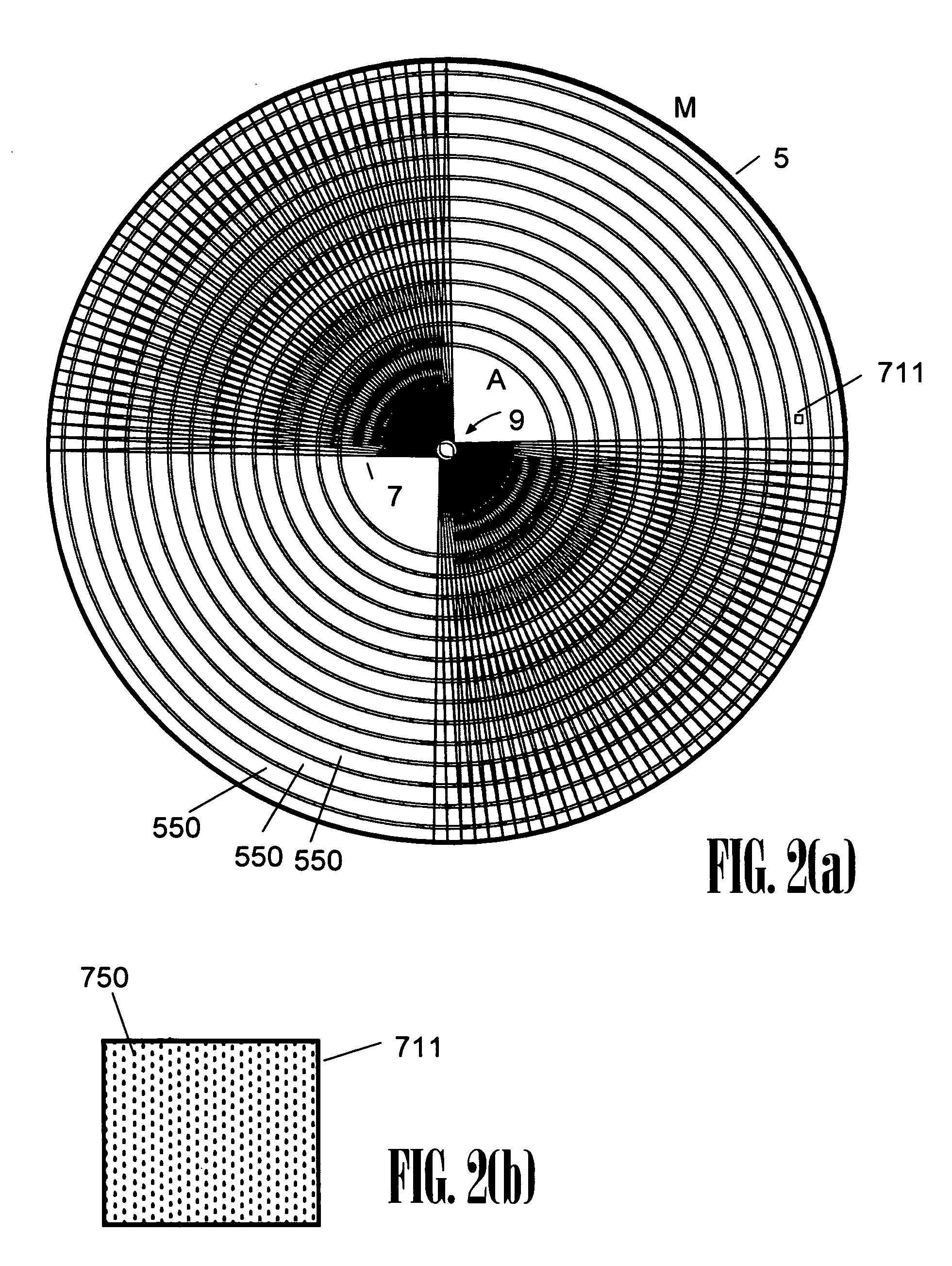
[0079]As disclosed in previous applications and included herein by reference, a wagon wheel optical cavity of the present invention is preferably formed as a thin-film Bragg reflector accordingly formed as a surface of revolution, wherein a preferred mode, which in one sense may be viewed as similar to a walk-off mode in a conventional confocal cavity, is, instead, a high-Q mode by virtue of rotating in (or walking around) the cont...


PUM


Abstract

A laser cavity structure is disclosed which pertains to laser resonator geometries possessing circular symmetry, such as in the case of disk or spherical lasers. The disclosed invention utilizes a very-high finesse Bragg reflector (VHF-BR) thin film reflectors of many layer pairs of very small refractive index difference, the VHF-BR deposited on a surface of revolution, thereby forming an optical cavity. These dielectric reflectors are disposed in such a way as to allow selection of preferred low order modes and suppression of parasitic modes while allowing a high cavity Q factor for preferred modes. The invention disclosed, in its preferred embodiments, is seen as particularly useful in applications requiring high efficiency in the production and coupling of coherent radiation. This is accomplished in a cavity design that is relatively compact and economical.

Description

[0001]This application is a continuation-in-part of U.S. application Ser. No. 12 / 082,887, filed Apr. 14, 2008, now issued, which is a divisional of U.S. application Ser. No. 10 / 968,280, filed Oct. 18, 2004, now issued, which is a continuation-in-part of U.S. application Ser. No. 09 / 839,254, filed Apr. 20, 2001, now issued, which claims benefit of U.S. Prov. Appl. No. 60 / 236,446, filed Sep. 29, 2000; all aforementioned applications are included herein by reference, in their entirety.BACKGROUND OF THE INVENTION[0002]1. Field of the Invention[0003]The present invention relates generally to the field of mode discrimination means in laser cavities, and in particular, mode discrimination in macroscopic cavities wherein a vast number of modes may otherwise be sustained.[0004]2. Description of the Related Art[0005]The present invention relates generally to the field of lasers and optical resonator design, and in particular, to the fields of disk and spherical lasers. Also, the invention rel...

Claims


Application Information

Patent Timeline
IPC IPC(8): H01S3/098
CPCH01S3/08H01S3/08059H01S3/08045H01S3/08009
Inventor HILLIARD, DONALD B.
Owner HILLIARD DONALD B
Why Eureka
Try Eureka