Spread illuminating apparatus

a technology of illumination apparatus and light source, which is applied in the direction of lighting and heating apparatus, planar/plate-like light guides, instruments, etc., can solve the problems of deteriorating brightness uniformity of illumination light emitted from the light emitting portion, reducing the utilization efficiency of light emitted from leds, etc., and achieves the effect of improving the brightness uniformity of illumination ligh

Active Publication Date: 2011-05-05
MINEBEAMITSUMI INC
View PDF4 Cites 21 Cited by
  • Summary
  • Abstract
  • Description
  • Claims
  • Application Information

AI Technical Summary

Benefits of technology

[0017]Since the light absorbing member is attached to the flexible printed circuit board so a to cover the slope portion, even if some light leaks from the slope portion, the leakage light can be absorbed by the light absorbing member thereby further improving the brightness uniformity of illumination light.

Problems solved by technology

Consequently, the utilization efficiency of light emitted from the LED is reduced and at the same time the brightness uniformity of illumination light emitted from the light emitting portion is deteriorated.
Also, the following problem is caused when the slope portion is provided toward the light entrance end surface of the light guide plate.

Method used


Image

  • Spread illuminating apparatus
  • Spread illuminating apparatus
  • Spread illuminating apparatus

Examples


Embodiment Construction

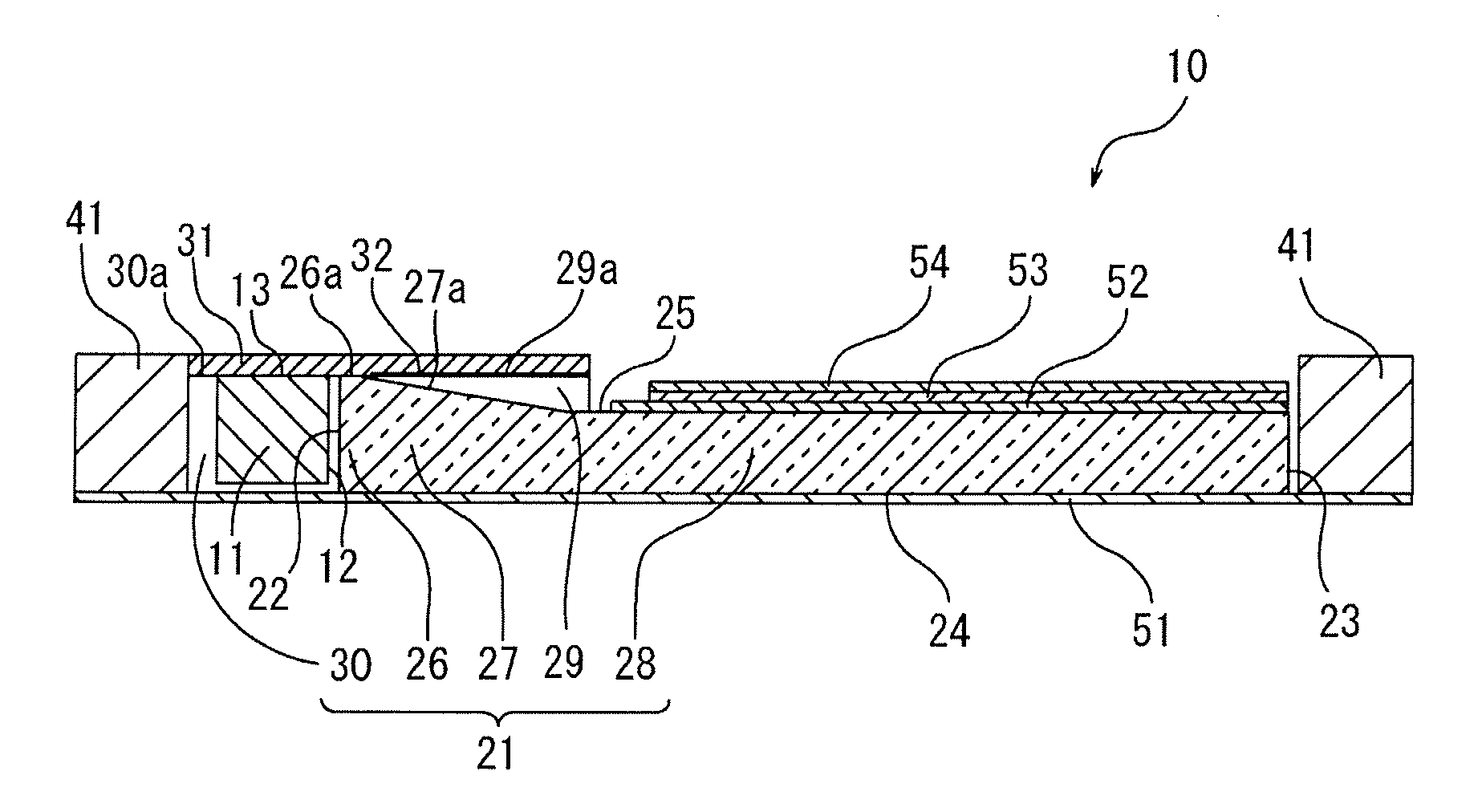
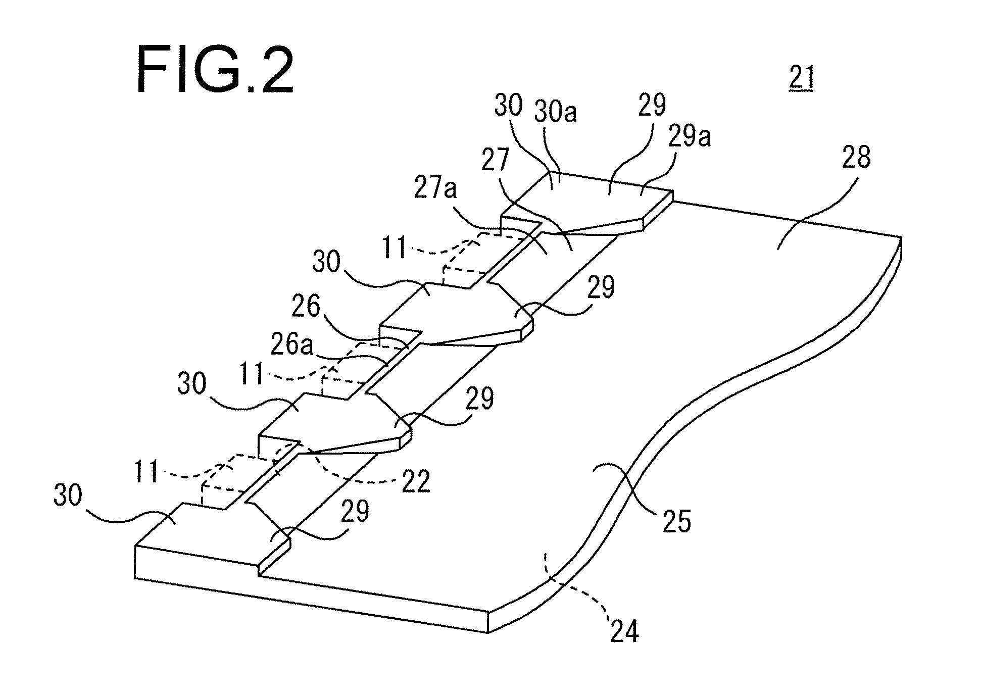
[0026]An exemplary embodiment of the present invention will be described with reference to the accompanying drawings. For the purpose of convenience, the drawings may exaggerate the shapes of constituent components as appropriate and therefore may not accurately reflect their dimensions. FIG. 1 shows a spread illuminating apparatus 10 according to an embodiment of the present invention.

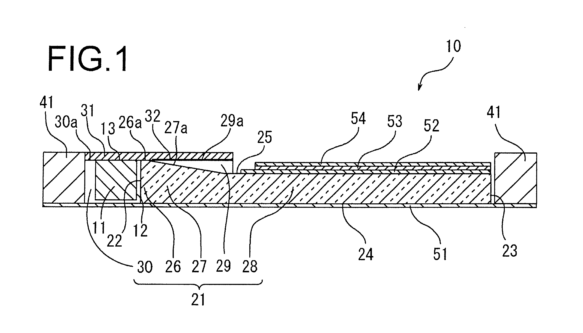
[0027]Referring to FIG. 1, the spread illuminating apparatus 10 includes a plurality of LEDs 11 as a light source (point light source), a light guide plate 21 configured to allow lights coming from the LEDs 11 to be emitted in a spread manner, an FPC (Flexible Printed Circuit Board) 31 having the LEDs 11 mounted thereon, and a frame 41 to enclose the LEDs 11 and the light guide plate 21.

[0028]In the present embodiment, each of the LEDs 11 is a pseudo white LED composed of a blue LED and a yellow fluorescent substance, has a rectangular body shape as a whole, and includes a side face functioning as a l...


PUM


Abstract

There is provided a spread illuminating apparatus including an LED, a light guide plate and a flexible printed circuit board on which the LED is mounted, wherein the light guide plate includes: a light entrance end surface at which the light source is disposed; a light emitting portion from which light emitted from the light source and introduced into the light guide plate exits out in a spread manner; a slope portion which is disposed between the light entrance end surface and the light emitting portion and which has a thickness decreasing toward the light emitting portion; and a seat block disposed at the slope portion and configured to fixedly receive the flexible printed circuit board. In the spread illuminating apparatus, the length of the slope portion is substantially 1.78 times as large as the largest thickness of the slope portion.

Description

BACKGROUND OF THE INVENTION[0001]1. Field of the Invention[0002]The present invention relates to a spread illuminating apparatus of side light type including a light guide plate, wherein a light source is disposed at a light entrance end surface of the light guide plate and light for illumination is emitted from a light emitting portion of the light guide plate in a spread manner, and relates more particularly to a spread illuminating apparatus including a light guide plate having a slope portion which is disposed toward the light entrance end surface and in which a thickness decreases gradually with an increase of distance from the light entrance end surface.[0003]2. Description of the Related Art[0004]A spread illuminating apparatus of side light type (back light), in which a plurality of LEDs (light emitting diodes) having a small dimension and excellent environmental compatibility are disposed along a light entrance end surface of a light guide plate, is widely used as an illumi...

Claims


Application Information

Patent Timeline
Patent Type & Authority Applications(United States)
IPC IPC(8): F21V7/22
CPCG02B6/0046G02B6/0018
Inventor KUNIMOCHI, TORUTAKAYAMA, RYOHEISUMA, AKIKO
Owner MINEBEAMITSUMI INC
Why Eureka
Try Eureka