Light source module with wavelength converting structure and the method of forming the same

a light source module and wavelength conversion technology, applied in the field of light source modules, can solve the problems of non-uniform illumination, mura effect, drawbacks generated by the increase of dimension, etc., and achieve the effects of reducing mura effect, reducing mura effect, and improving uniform light emission

Inactive Publication Date: 2009-08-06
KISMART
View PDF3 Cites 63 Cited by
  • Summary
  • Abstract
  • Description
  • Claims
  • Application Information

AI Technical Summary

Benefits of technology

[0008]One objective of the present invention is to provide a light source module comprising: an enclosure having a substrate formed therein; a plurality of LED (light emitting diode) dice disposed on the substrate; and a shared wavelength converting structure disposed on the enclosure to reduce mura effect and convert a first wavelength of the light from the plurality of LED dice into a second wavelength.
[0009]Another objective of the present invention is to provide a method for producing a light source module, the method comprises step of providing an enclosure having a substrate formed therein; the next step is to dispose a plurality of LED (light emitting diode) dice on the substrate; and a shared wavelength converting structure is disposed on the enclosure and over the plurality of LED dice to reduce mura effect and convert a first wavelength of the light from the plurality of LED dice into a second wavelength.
[0010]In combination with a light source, the shared wavelength converting structure may have a transparent plate with a wavelength converting layer thereon to improve the uniformity of the light emission and reduce the mura effect. The present invention can improve the uniformity of brightness of a flat light source with multiple lighting elements and provide a flat source of visible light with a large area. Further, the present invention also simplifies the manufacture process for forming phosphor powders on the plate. The light source of the present invention can further be applied in a backlight module for a display panel with a larger scale by simple means.

Problems solved by technology

In order to providing large scale illumination, some drawbacks are generated with the increase of the dimension, “Mura effect” is one of the issues.
Especially, when the large-scale illumination is employed with a plurality of lighting units, the mura effect is more serious than ever if the number of lighting units is insufficient therefore the distance between lighting units is too large, it causes the illumination is non-uniform.
The existing sources of visible light either lack the maturity in terms of producing a large-scale light source due to their innate limitations in production, both failing to convert light in a large area using simple and inexpensive means.

Method used


Image

  • Light source module with wavelength converting structure and the method of forming the same
  • Light source module with wavelength converting structure and the method of forming the same
  • Light source module with wavelength converting structure and the method of forming the same

Examples


Embodiment Construction

[0019]Some sample embodiments of the invention will now be described in greater detail. Nevertheless, it should be recognized that the present invention can be practiced in a wide range of other embodiments besides those explicitly described, and the scope of the present invention is expressly not limited except as specified in the accompanying claims. Then, the components of the different elements are not shown to scale. Some dimensions of the related components are exaggerated and meaningless portions are not drawn to provide clearer description and comprehension of the present invention.

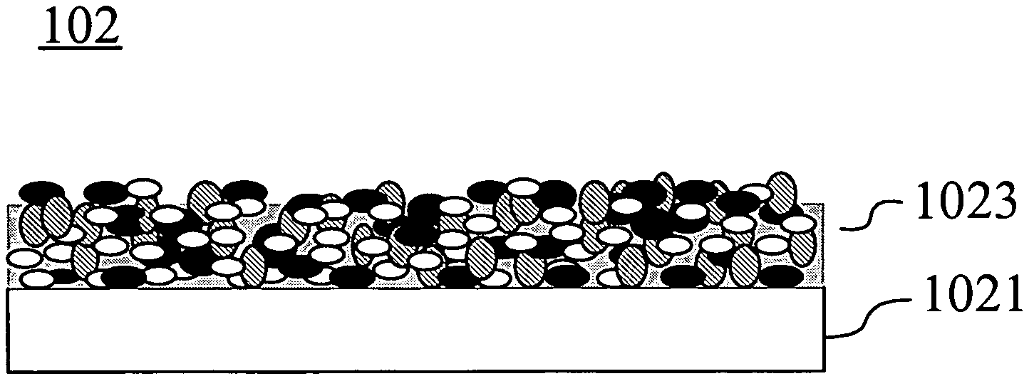
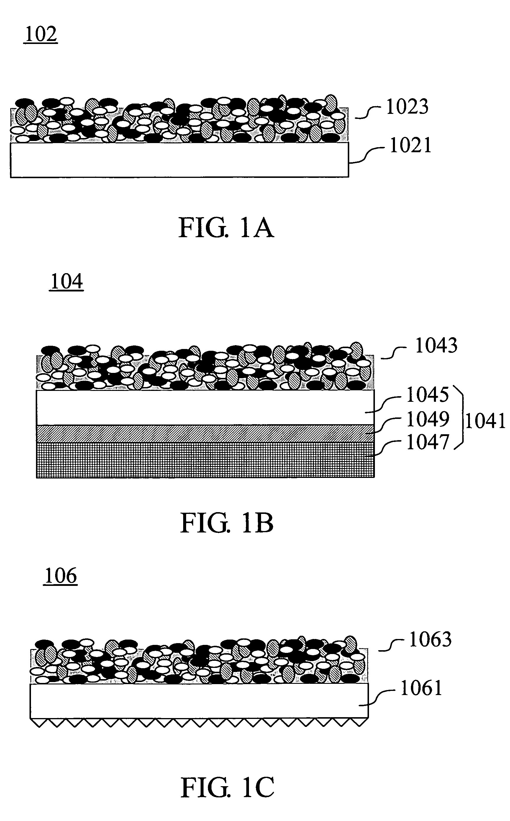
[0020]The present invention is to dispose the shared wavelength converting structure over the plurality of LED dice in order to improve the uniformity of the light emission and reduce the mura effect resulted from light source consisting of multiple lighting elements, further, since the phosphor powers are coated on the shared plate instead of over the individual die (multiple lighting elements), ...


PUM


Abstract

A light source package module with a wavelength converting structure is provided. The light source package module comprises a frame having a substrate and sidewalls formed on the substrate. A plurality of LED dice is disposed on the substrate, and there is a space between each of the LED dice. A wavelength converting structure is disposed on above the plurality of LED dice and the sidewalls. The light source package can provide a flat light source with a large emitting area can be made in simply as well. Additionally, the present invention further relates to the application of a backlight module.

Description

BACKGROUND OF THE INVENTION[0001]1. Field of the Invention[0002]The invention relates to a light source module, more particularly to a light source with a shared wavelength converting structure and the method of forming the same.[0003]2. Descriptions of the Related Art[0004]The trend for light sources used in displays has become increasingly flat with large emitting areas. The flat light sources with large emitting areas are very important for backlight modules in large-sized flat panel liquid crystal displays. For various conventional light sources, the means currently used to provide visible light through energy / wavelength conversion includes cold cathode fluorescent lamps (CCFL), external electrode fluorescent lamps (EEFL), light emitting diodes (LED), carbon nanotubes (CNT), flat fluorescent lamps (FFL), and organic light emitting displays (OLED).[0005]In order to providing large scale illumination, some drawbacks are generated with the increase of the dimension, “Mura effect” i...

Claims


Application Information

Patent Timeline
Patent Type & Authority Applications(United States)
IPC IPC(8): H01L33/00H01L33/50
CPCG02F1/133603G02F2001/133614H01L25/0753H01L33/505H01L2924/0002H01L2924/00G02F1/133614
Inventor HUANG, HSIN-TAOHSIAO, CHUN-CHUNG
Owner KISMART
Why Eureka
Try Eureka